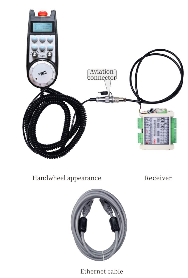
1. Use a 6-core aviation plug cable for connection, with a handwheel cable length of 10 meters.
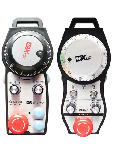
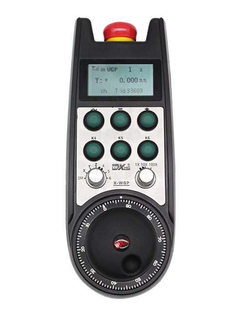
2. The handwheel screen can display system workpiece coordinates, mechanical coordinates,feed rate, axis selection, magnification, and other information.
3. Support emergency stop button, switch IO signal output, and the hand wheel shutdown emergency stop is still valid.
4. Supports 6 custom buttons, switch IO signals, and can output signals to the system through IO wiring or communication.
M
Description
1. Nthuts'i ñut'i producto
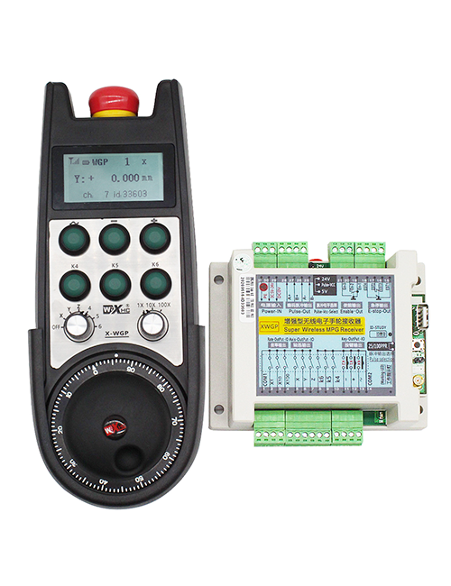
Volante electrónico ar gi japu̲'be̲fi pa ar guía manual, posicionamiento, alineación herramientas, ne ma'ra ja ya máquinas bo̲jä nu'u̲ CNC. Nuna ar modelo volante electrónico ge 'nar Siemens real display cable volante electrónico. Volante xi conectado jar interfaz X 130 ko ya Siemens a través de 'nar cable red, ne ya coordenadas ko ya leen ne muestran jar pantalla LCD volante a través de comunicación nthuts'i nkohi S7. Volante 'nehe tsa̲ da controlar selección ejes ko ya, magnification, botones, ne ma 'ra ya señales a través de comunicación.
2.Características funcionales ar producto
1. Use a 6-core aviation plug cable for connection, with a handwheel cable length of 10 meters.
2. The handwheel screen can display system workpiece coordinates, mechanical coordinates,feed rate, axis selection, magnification, and other information.
3. Support emergency stop button, switch IO signal output, and the hand wheel shutdown emergency stop is still valid.
4. Supports 6 custom buttons, switch IO signals, and can output signals to the system through IO wiring or communication.
5. Supports 6 or 8 axis control, with switch IO signals that can be output to the system through IO wiring or communication.
6. Supports 3 or 4 niveles control aumento, with switch IO signals that can be output to the system through IO wiring or communication.
7. Support pulse encoder, 100 pulsos yá vuelta, pe emitir señales ko ya a través de cableado pulso AB.
8. Soporta nthuts'i nkohi Siemens S7 ne Siemens 828D, 840DSL, 'NA ne ma'ra sistemas modelos.
3. Product specifications
| Volante 'be̲fi tensión fuente alimentación 'be̲fi | DC24V yá 1A |
| Voltaje fuente alimentación ar receptor | DC24V yá 1A |
| Rango carga salida IO receptor | DC24V |
| Longitud cable extremo rueda 'ye̲ | 10m |
| Longitud cable extremo ar receptor | 1m |
| Longitud ar cable red extremo receptor | 3m |
| Mpat'i funcionamiento | -25° c<X<55° c |
| Altura anti caída | 1m |
| Yá 'bede ya botón personalizado | 6 |
| Dimensiones ar producto | 233*90.7*77.4(mm) |
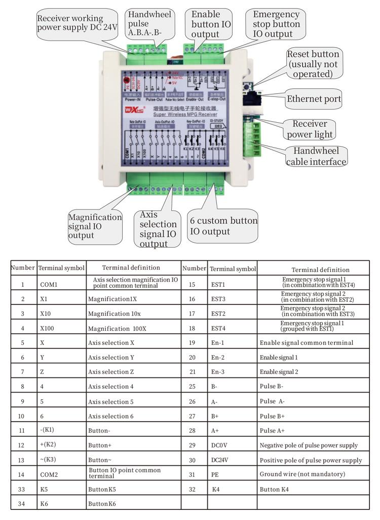
4.Product function introduction
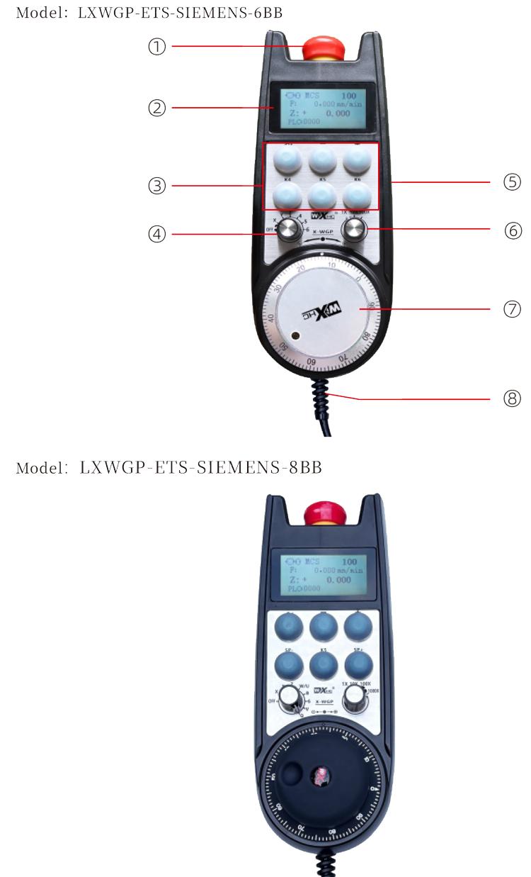
hñeti:
Botón parada emergencia:
Press the emergency stop button, yoho ya conjuntos salidas IO parada emergencia ja ar receptor ar desconectarán, ga̲tho ya 'befi ar volante ar desactivarán.
'mefa xta soltar parada emergencia salida IO ja ar receptor xí cerrada, 'mefa xta soltar ar parada emergencia salida IO ja ar receptor xí cerrada, ga̲tho ya 'befi ar volante ar restauran.
(2) pantalla pantalla:
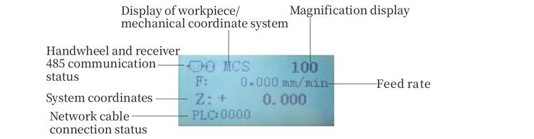
PLC: 0000 indica ke ar cable red hingi 'bu̲i conectado, PLC: 1010 indica ke cable red xi conectado ko ya éxito ko ya PLC.
PLC: 1110 o̲t'e nt'ot'i exitosa datos ko ya volante, PLC: 0001 o̲t'e conexión exitosa ja ar ordenador.
(3) botón personalizado:
6 custom buttons, kadu 'na vinculado ja 'nar punto salida IO ja ar receptor, 'nehe conectado ko ya a través de comunicación.
(4) interruptor selección ejes :
Interruptor selección ar eje to mpa̲ti eje yá 'ñäni controlado ir nge ar volante.
(5) botón habilitar :
Mantenga presionado ya da botón habilitar ja ga̲ yoho ya xe̲ni pa activar codificador pulso sacudiendo nä'ä. Ne yoho ya Hmunts'i ja ar receptor permiten salida IO pa conducir, Suelte botón habilitar pa habilitar salida IO pa desconectar.
(6) interruptor aumento:Interruptor ar aumento tsa̲ da mpa̲ti ar aumento
Controlado ir nge ar volante.
(7) codificador pulso:
Presione ne mantenga pulsado ar botón habilitar, agitar codificador pulso, emitir 'nar señal pulso, Ne controlar yá 'ñäni ar eje ar máquina.
(8) Cable volante:
Cable conecta ar volante ne ar receptor, Enchufe aviación, Utilizado pa fuente alimentación volante ne comunicación.
5. Product accessory diagram
6. Product Installation Guide
6.1 Pasos instalación producto
6.1 Pasos instalación producto
1. Instalar ar receptor armario eléctrico a través de ya orificios tornillo ja ya esquinas goho.
2. Consulte ma diagrama cableado receptor ne comparar ko ár configuración jar sitio. Connect the device to the receiver through cables and connect the receiver to the X130 interface of the system using Ethernet cables.
3. After fixing the receiver, install the aviation plug base at the handwheel opening position on the panel, and plug the other end of the base into the handwheel interface on the receiver. Then insert the aviation plug of the handwheel cable into the base and tighten the fixing device.
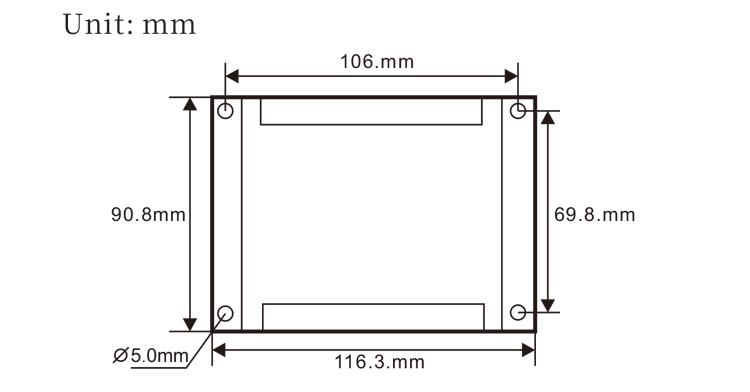
6.2 Receiver installation dimensions
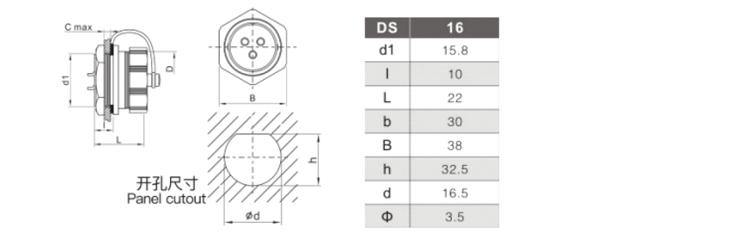
6.3 Installation dimensions of aviation plugs
6.4 Receiver Wiring Reference Diagram
 7.Product Operation Instructions
7.Product Operation Instructions
1. When the receiver is powered on and the working indicator light of the receiver flashes, connect the receiver to the computer with a network cable, set the fixed IP address of the computer, and use the network configuration tool software to set the network parameters of the handwheel function. For specific setting methods, refer to the “LXWGP-ETS Wired Handwheel User Manual”.
2.After the receiver is set up, the system needs to program a PLC program. Please refer to the “LXWGP-ETS Different Siemens Numerical Control System Setting Methods” and PLC program routine materials for details.
3.After completing the above settings, take the receiver to the machine electrical cabinet and install it. Pull out the network cable from the computer and plug it into the X130 interface of the system.Connect the receiver power supply and pulse line.3.
4.After completing the above settings, take the receiver to the machine electrical cabinet and install it. Pull out the network cable from the computer and plug it into the X interface of the system. Connect the receiver power supply and pulse line.
5. Select axis selection: Switch the axis selection switch and select the axis you want to operate on.
6. Select magnification: Mpa̲ti interruptor aumento ne seleccione ar ampliación da t'ot'e.
7. Eje móvil: Presione ne mantenga pulsado ar botón habilitar, select the axis selection switch, select the magnification switch, and then rotate the pulse encoder to rotate the positive moving axis clockwise and the negative moving axis counterclockwise.
8. Press and hold any custom button to turn on the IO output of the corresponding button in the receiver, and release the button to turn off the output.
9. Press the emergency stop button, the corresponding emergency stop IO output of the receiver will be disconnected, the handwheel function will be disabled, release the emergency stop button, the emergency stop IO output will be closed, and the handwheel function will be restored.
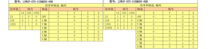
8.Product Model Description

① LXWGP represents a wired appearance style, and the receiver communication interface
is an Ethernet interface.
② : Represents Siemens system specific.
③ : represents the number of axis selection switches, represents axes, and represents
axes.
④ : represents the type of axis selection and magnification signal, A represents
point-to-point output signal, and B represents encoded output signal.
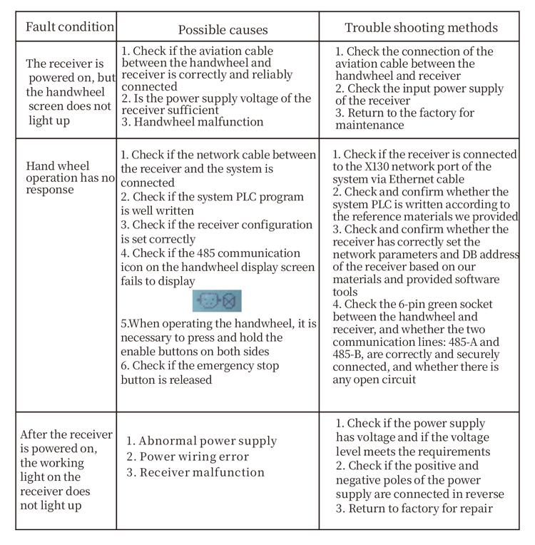
9.Product trouble shooting
10.Maintenance
1. Please use it in a dry environment at room temperature and pressure to extend its service life.
2. Please avoid using in abnormal environments such as rain and water bubbles to extend the service life.
3. Please keep the appearance of the handwheel clean to extend its service life.
4. Please avoid squeezing, falling, bumping, etc.. to prevent damage to the precision components inside the handwheel or accuracy errors.
5. If not used for a long time, please store the handwheel in a clean and safe place.During storage and transportation, attention should be paid to moisture and shock resistance.
11. Safety Information
1. Please read the instructions carefully before use and prohibit non professionals from operating.
2. If any abnormal situation occurs with the handwheel, please stop using it immediately and troubleshoot. Before troubleshooting, it is forbidden to use the faulty handwheel again to avoid safety accidents caused by unknown handwheel faults;
3. If repair is required, please contact the manufacturer. If the damage is caused by self repair, the manufacturer will not provide warranty
-500x650.png)