Описание
1. Въведение на продукта
The remote control for automatic cutting of track car rope saw is suitable for track type rope saw
cutting machines. It uses the 485 Modbus RTU protocol to control the left and right track frequency
converters, as well as the large motor frequency conversion speed control start and the front, rear,
left and right direction controllers. And it can read the working current of the large motor frequency
converter through the 485 Modbus RTU protocol. By analyzing and comparing the current of the
large motor, the speed of the left and right tracks can be automatically adjusted in real time to
achieve automatic cutting function.
2. Функционални характеристики на продукта
1. Adopting 433MHz wireless communication technology, с безжично работно разстояние от 100 метри.
2. Приемете функцията за автоматично прескачане на честотата и използвайте 32 sets of wireless remote controllers
simultaneously, без да се засягат взаимно.
3. Supports all frequency converters with 485 Modbus RTU protocol, and currently compatible frequency
converter brands include:Шанхай Xielin, Фуджи, Huichuan, Zhongchen, Invt, и . For brands
that are not compatible, please contact us for customization.
4. Регулиране на скоростта на подкрепа, Стартиране, и текущо четене на големи двигателни честотни преобразуватели.
5. Поддръжка на ляв и десен път Регулиране на честотната скорост на конвертора, Стартиране, отпред, Назад, Ляв и десен контрол.
6. Подкрепете линейна корекция на честотните преобразуватели на лявата и дясната пътека, за да поддържате машината да ходи в a
права линия.
7. Support automatic cutting function of rope saw, automatically adjust the left and right track speed in
real time according to the current information of the large motor.
8. It is also compatible with direct IO output control for motor start and stop, and analog voltage output
control for motor speed.
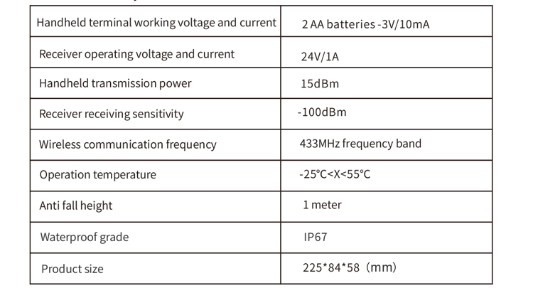
3. Спецификации на продукта
4. Представяне на функцията на продукта
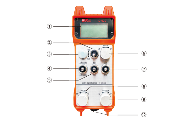
Бележки:
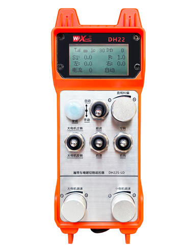
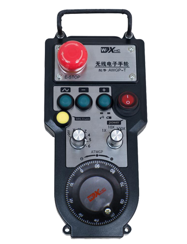
①Screen дисплей:
②mode превключвател:
③Enable:
Комбинирани бутони, Някои операции изискват задържане на бутона за активиране за работа,see the instructions for each switch for details.
④Large motor switch:
Използване на 3-степенна превключвател за нулиране, Издърпването на този превключвател може да контролира напред и обратното въртене на големия двигател. След като го пуснете, Държавата ще остане, и на екрана ще има съответни дисплеи. The S1↑ arrow indicates forward rotation, and the S1 ↓ arrow indicates everse rotation.
⑤mall двигател напред/обратна превключвател:
The small motor is equipped with a 3-speed self-locking switch in front of it. Pressing the enable button and pulling this switch can control the small motor to move forward and backward, and the corresponding display will appear on the screen.The ↑↑ arrow represents forward, and the ↓↓ arrow represents backward.
⑥ Straight line correction:
Използване на копче за енкодер с мулти завой, press the enable button, turn the knob right, and display the straight line correction: Df: The left turn knob increases by 1 unit per rotation, and the left
motor speed increases by 0.1 единица; Завъртете наляво копчето, Дисплей за корекция на права линия: Df: On the right, every turn of the knob increases by 1 единица, and the speed of the right motor increases
by 0.1 единица.
⑦Small motor turning switch:
Използване на 3-степенна превключвател за нулиране, при ръчно опериране, Малкият двигател може да бъде контролиран, за да завие наляво или надясно. Веднъж пуснат, the remote control will automatically stop this action. In the forward state, when this switch is turned, the corresponding display will appear on the screen. The ←↑ arrow indicates left turn, and the ↑→ arrow indicates right turn.When in reverse mode, turn this switch and the corresponding display will appear on the screen. The ←↓ arrow indicates left turn, and the ↓→ arrow indicates right turn.
⑧ Голяма регулация на скоростта на двигателя:
Използване на копче за енкодер с мулти завой, rotating 1 решетка всеки път, Стойността на скоростта на големия двигател се променя приблизително 0.2 единици. Fast rotation can quickly modify the speed value of the large motor.
⑨ Small motor speed regulation:
Използване на копче за енкодер с мулти завой, В ръчен режим, press the enable button and then rotate one grid at a time,the speed value of the left and right small motors changes by about 0.1 единици, and quick rotation can quickly modify the speed value of the small motor.In automatic mode, press the enable button and rotate one grid at a time,the speed limit value F of the small motor changes by approximately 0.1 единици. Rapid rotation can quickly modify the speed limit value of the small motor.
⑩ Remote control power switch
Екранът за дисплей от дистанционно управление е включен.
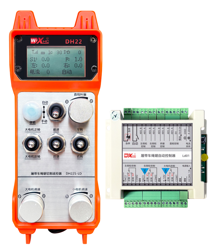
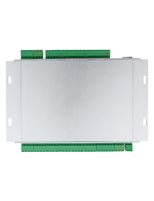
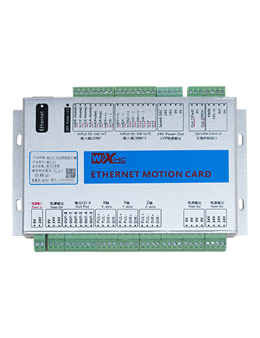
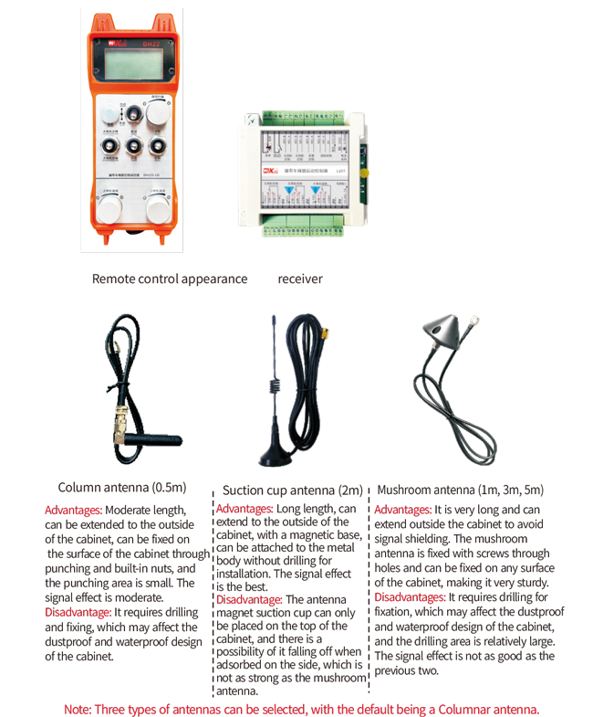
5. Диаграма за аксесоари за продукти
6. Ръководство за инсталиране на продукти
6.1 Стъпки за инсталиране на продукта
1. Инсталирайте приемника в електрическия шкаф през катарамата на гърба, или го монтирайте в шкафа през отворите за винтове в четирите ъгъла на приемника.
2. Обърнете се към нашата схема на свързване на приемника и я сравнете с вашето оборудване на място. Connect the equipment to the receiver through wires.
3. След фиксиране на приемника, it is necessary to connect the antenna equipped with the receiver and install or place the outer end of the antenna outside the electrical cabinet. Препоръчва се да го поставите в горната част на електрическия шкаф за най -добрия ефект на сигнала. It is forbidden to leave the antenna unconnected or place it inside the electrical cabinet, as it may cause the signal to be unusable.
4. Накрая, install the battery on the remote control, Затегнете капака на батерията, and turn on the power switch of the remote control. After the remote control display screen shows the normal
working interface, remote control operations can be performed.
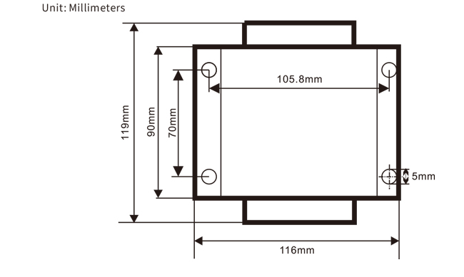
6.2 Размери за инсталиране на приемник
6.3 Референтна диаграма на проводника на приемника
7. Инструкции за експлоатация на продукта
7.1 Настройки на параметъра за дистанционно управление
Method to enter the remote control backend parameters:
Turn the mode switch to manual mode, регулирайте скоростта на малкия двигател до 25 on both sides, или 0, 10, 20, 40, 50 on all sides, and continuously turn the forward switch of the large motor up 3 times and down 3 пъти;
Използвайте “Малък контрол на скоростта на двигателя” knob to flip pages, press the enable button, and then turn the small motor speed control knob to modify parameters. After modification, обърнете страницата до края,изберете “Save” to exit, and press the enable button to exit the menu;
Параметрите са както следва:
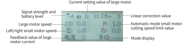
Максимален ток: feedback range of large motor current, set range 15-200A, по подразбиране 100;
Параметри на контролното управление: Автоматичен режим, small motor automatically accelerates faster or slower,Колкото по -малко е по -бързо, set range 200-1500, по подразбиране 800;
Параметър за забавяне: Set the upper limit that allows the motor speed to change. Когато токът се промени извън тази стойност, the deceleration will occur. The smaller, the faster the deceleration of the left and right motors, с диапазон от 05-12 and a default of 06;
Ускорение А1: The larger the motor speed, the faster it increases, с диапазон от 00-06 and a default of 01;
Намаляване А2: The larger the motor speed, the faster it decreases, с диапазон от 00-06 and a default of 02;
Активиране на регулиране на скоростта: Does the small motor speed regulation need to be enabled? 00 does not enable, 01 enables, default is 01;
Започнете самозаключването: Does the large motor automatically maintain self-locking after the forward and reverse switches are released? 00 does not hold, 01 holds, по подразбиране 01
Максимално ходене: maximum speed of left and right motors, обхват 10-100, по подразбиране 50;
Ток на рязане: maximum cutting current, displayed on the screen as IC value, обхват 15-160, по подразбиране 30,
corresponding to IC: 30 displayed on the screen. The upper limit of this parameter is 80% of the maximum current;
Ограничение на скоростта по подразбиране: The default small motor automatic cutting speed when turned on is within the range of 0-100, with a default of 10. The screen displays F1.0, and this parameter is only accurate when the maximum walking is set to 50.
Автоматичен режим: Set to 00, the automatic/manual switch is a mode switch. Set to 01, the automatic/manual switch is set to the automatic position, the display screen shows lighting, and the automatic terminal output on the receiver is closed. When set to manual, the automatic output terminal is disconnected;
Speed limit deviation: The upper limit of the automatic cutting speed of the small motor ranges from 00 да 200, with a default of 60 and a corresponding display of 6.0 on the screen; Upper limit of display value=speed limit offset x 0.1;
Максимален хост: maximum speed of the large motor, обхват 10-100, по подразбиране 50;
Mbus equipment (Задължително): Selection of large motor frequency converter model, обхват 00-03, по подразбиране 03;
00- Shanghai Xielin 01-Fuji
02-INVT 03-Inovance(Zhongchen, Робикон)
SBUS оборудване (Задължително): Избор на модел за преобразувател на малък двигател, обхват 00-05, по подразбиране 03;
00- Shanghai Xielin 01-Fuji
02-INVT 03-Inovance(Zhongchen, Робикон)
04-Anchuanda 05-NONE
7.2 Настройка на параметрите на честотния конвертор
1. Избор на команден източник: Комуникационен канал за комуникация
2. Избор на източник на основна честота: Дадена комуникация
3. Скорост на бод: 19200
4. Формат на данни: Без проверка, формат на данни<8-N-1>
5. Местен адрес: Задайте преобразувателя на лявата честота на 1, правилния честотен преобразувател към 2, и
the large motor frequency converter to 3
7.3 Инструкции за експлоатация на дистанционно управление
1. Мощност на машината, Включете дистанционното управление, enter the remote control backend, set the
remote control backend parameters, mainly setting the small motor and large motor frequency
converter models: (Пропуснете тази стъпка, ако производителят на машината вече го е настроил);
2. Задайте параметрите на честотния конвертор (skip this step if the machine manufacturer
has already set it);
3. Задайте дистанционното управление в ръчен режим, and then use the remote control to move the machine to
the working position;
4. В ръчен режим, set the cutting current of the large motor to IC and the speed of the large motor
5. Превключете в автоматичен режим и задайте стойността на ограничението на скоростта на рязане F за малкия двигател;
6. В автоматичен режим, Завъртете големия превключвател на двигателя напред, за да стартирате големия двигател, then turn
the small motor switch to forward or reverse, and the remote control enters automatic cutting
mode to start cutting.
8.Отстраняване на проблеми с продукта
9.Поддръжка
1. Моля, използвайте го в суха среда при стайна температура и налягане, за да удължите експлоатационния си живот.
2. Моля, избягвайте да използвате в ненормални среди като дъжд и водни мехурчета, за да удължите експлоатационния живот.
3. Моля, запазете отделението за батерии и металните шрапнели чисти.
4. Моля, избягвайте да повредите дистанционното управление поради притискане и падане.
5. Ако не се използва дълго време, please remove the battery and store the remote control and battery in a clean
and safe place.
6.По време на съхранение и транспортиране, Трябва да се обърне внимание на влагата и устойчивостта на шок.
10. Информация за безопасността
1. Моля, прочетете внимателно инструкциите преди употреба и забранявайте на не специалистите да работят.
2. Please replace the battery in a timely manner when the battery is too low to avoid errors caused by
insufficient power, което може да доведе до това, че дистанционното управление не може да работи.
3. Ако се изисква ремонт, Моля, свържете се с производителя. Ако щетите са причинени от самостоятелен ремонт, the manufacturer
will not provide warranty.