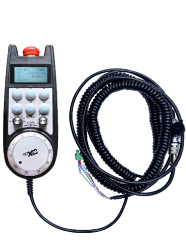
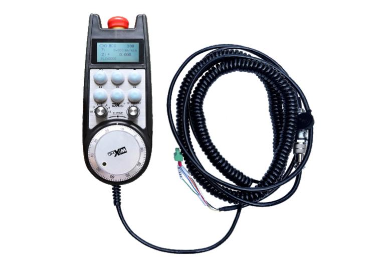
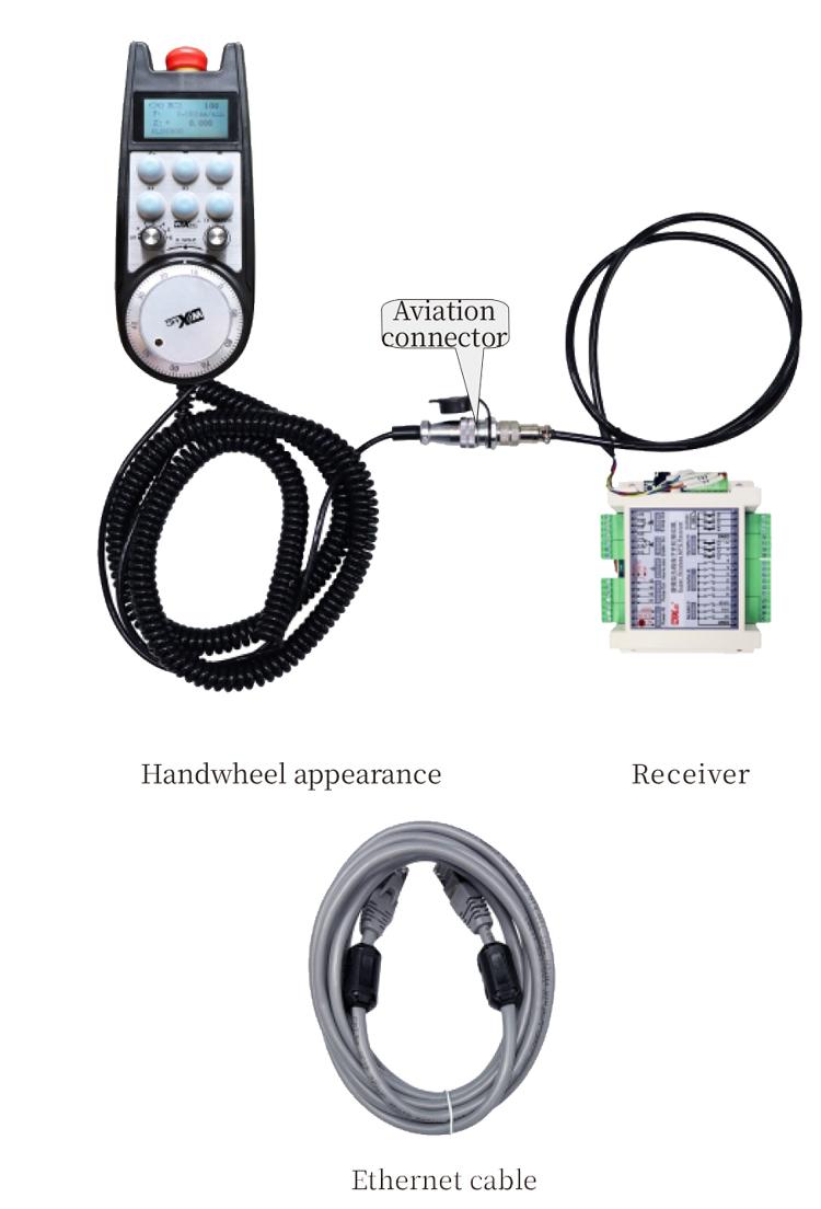
1. Jiri 6-core avition Plug ga-eriri maka njikọ, jiri nwayọ nwayọ 10 mize.
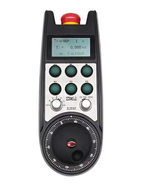
2. Ihuenyo dị mma nwere ike igosipụta usoro nhazi ụlọ ọrụ, Nchịkọta Nhazi,Nri nri, Nhọrọ Axis, ogo, na ozi ndi ozo.
3. Kwadebe bọtịnụ Mberede, Gbanwee Ntanetị Ntanetị, na aka na-emechi emechi mberede.
4. Na-akwado 6 bọtịnụ omenala, Gbanwee akara io, ma nwee ike mmepụta akara na sistemụ site na io Wiretion ma ọ bụ nkwukọrịta.
Akwụkwọ ntuziaka na-enye nkwado
Nkowa
1. Nmkpọ Okwu mmalite
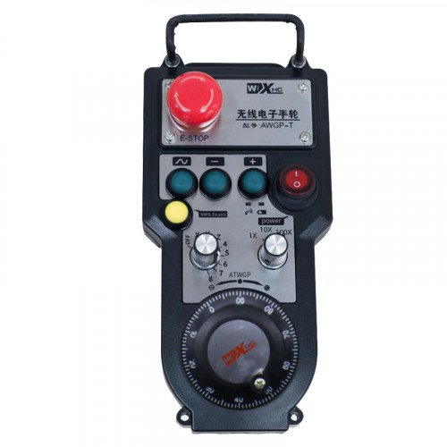
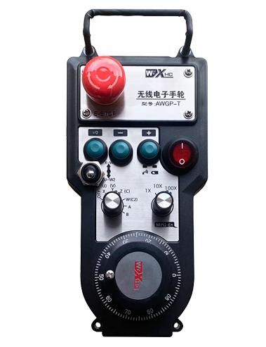
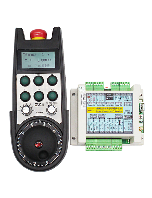
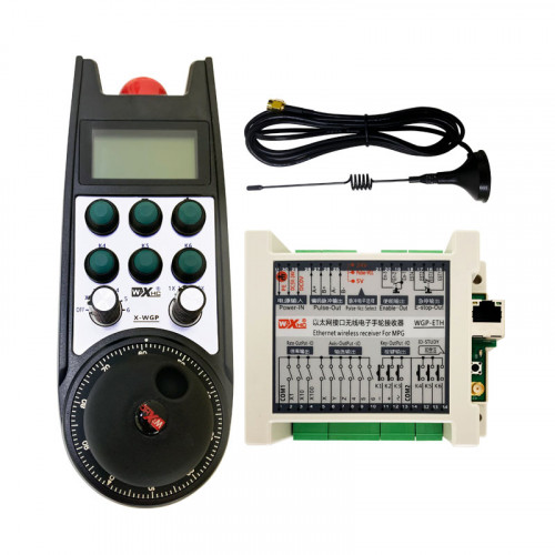
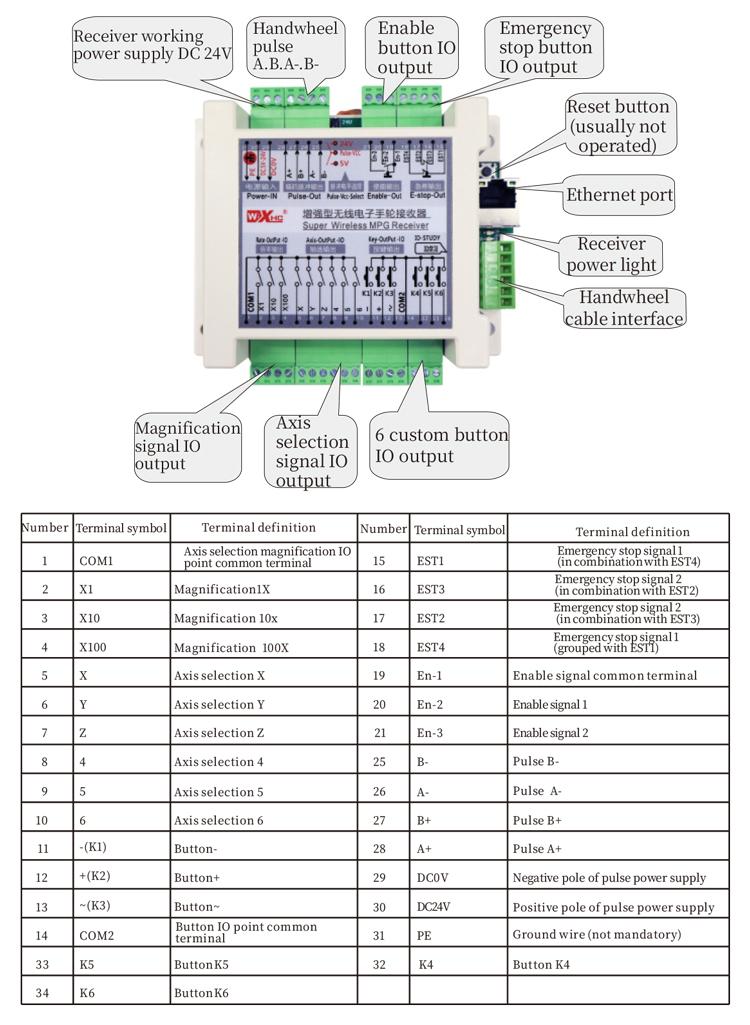
A na-eji ngwa elektrọniki maka ntuziaka ntuziaka, Iche, ntinyeaka, na arụmọrụ ndị ọzọ na ngwaọrụ igwe CNC. Ihe nlereanya nke elektrọnik a bụ onye na-azụ ihe ngosi. A na-ejikọ aka na-ejikọ ya na interface X130 nke Sistem Sistem site na eriri netwọkụ, A na-agụ usoro nhazi sistemụ ma gosipụta na ihuenyo LCD nke aka site na nkwukọrịta S7. Akara ahụ nwekwara ike ịchịkwa usoro Axis, ogo, Buttons, na-agbanwe agbanwe site na nkwukọrịta.
2.Njirimara arụmọrụ
1. Jiri 6-core avition Plug ga-eriri maka njikọ, jiri nwayọ nwayọ 10 mize.
2. Ihuenyo dị mma nwere ike igosipụta usoro nhazi ụlọ ọrụ, Nchịkọta Nhazi,Nri nri, Nhọrọ Axis, ogo, na ozi ndi ozo.
3. Kwadebe bọtịnụ Mberede, Gbanwee Ntanetị Ntanetị, na aka na-emechi emechi mberede.
4. Na-akwado 6 bọtịnụ omenala, Gbanwee akara io, ma nwee ike mmepụta akara na sistemụ site na io Wiretion ma ọ bụ nkwukọrịta.
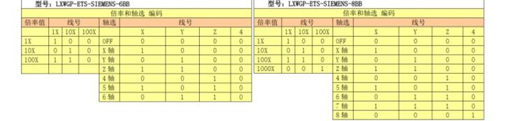
5. Na-akwado 6 ma ọ bụ 8 Njikwa Axis, Site na ngbanwe IO Io nwere ike iwepụta na sistemụ site na Io Werring ma ọ bụ nkwukọrịta.
6. Na-akwado 3 ma ọ bụ 4 Ọchịchọ nke njikwa elu, Site na ngbanwe IO Io nwere ike iwepụta na sistemụ site na Io Werring ma ọ bụ nkwukọrịta.
7. Nkwado Pluner, 100 pulses / ntụgharị, nwere ike imepụta akara na sistemụ site na ab Pulling Werring.
8. Na-akwado Siemens S7 Protocol na Siemens 828D, 840Dil, Otu na usoro ihe nlereanya ndị ọzọ.
3. Nkọwapụta ngwaahịa
| Aka ike na-arụ ọrụ ike ọkụ voltaji | Dc24v / 1a |
| Onye na-anabata ike na-enye ọkụ ọkụ | Dc24v / 1a |
| Nnata Io Io Mmepụta | Dc24v |
| Aka eriri ụkwụ | 10m |
| Ogologo eriri afọ | 1m |
| Ogologo ntaneti na-akwụ ụgwọ | 3m |
| Okpomọkụ | -25℃<Nke X<55℃ |
| Anti-Fall Hear | 1m |
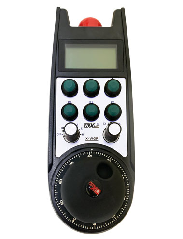
| Obere akara | 6 |
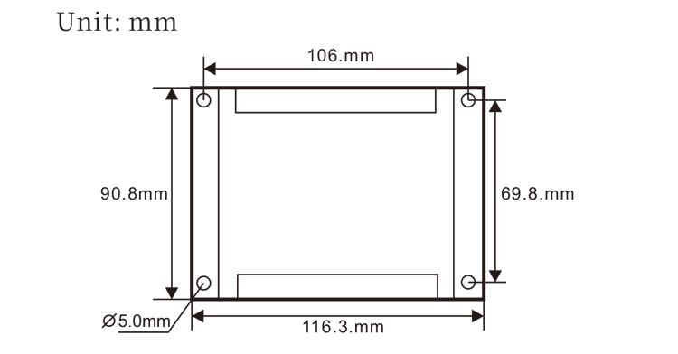
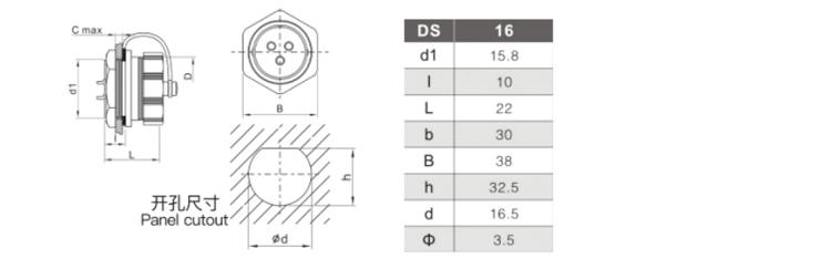
| Akụkụ ngwaahịa | 233*90.7*77.4(Mm) |
4.Mmepe mmeghe nke ngwaahịa
Dee:
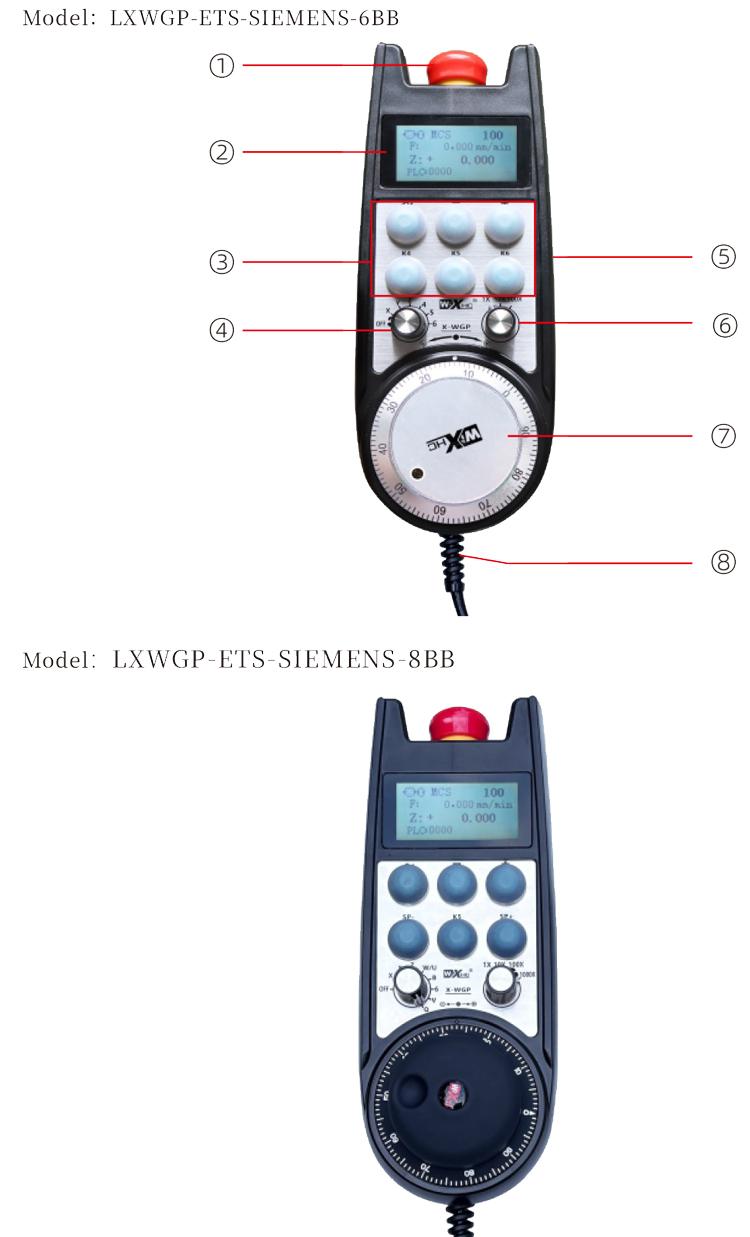
Bọtịnụ Mkpuchi mberede:
Pịa bọtịnụ Mkpuchi mberede, na usoro abụọ a na-eme na mberede na-emepụta ihe na nnata ga-ahapụ, na ọrụ niile nke aka ga-abaghị uru.
Mgbe ị hapụsịrị ịkwụsị ihe mberede ahụ, Mberede na-akwụsị ihe na-emepụta na onye na-anabata ya, A na-eweghachi ọrụ niile nke aka.
Ngosipụta ihuenyo:
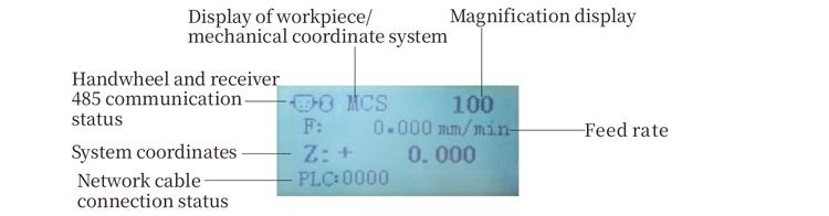
Plc: 0000 na-egosi na eriri eriri netwọk anaghị ejikọ, Plc: 1010 na-egosi na a na-ejikọrịrị eriri netwọkụ na sistemụ plc.
Plc: 1110 na-anọchi anya ederede nke data sistemụ na aka, Plc: 0001 na-anọchi anya njikọ na kọmputa.
③ Auty na-ejikọ:
6 bọtịnụ omenala, onye ọ bụla kwekọrọ na isi ihe mmepụta ihe na onye na-anabata ya, jikọọ na sistemụ site na nkwukọrịta.
④ Axis Nhọrọ:
Ntinye nhọrọ axis nwere ike ịgbanyụgharịgharị nke axis na-achịkwa site na aka.
Mee bọtịnụ:
Pịa ma jide na-eme ka ọ dị na akụkụ abụọ iji mee ka ọ bụrụ onye na-apụ apụ site na ịma jijiji. Na ndị otu abụọ ahụ na nnata na-enyere m aka imepụta, hapụ bọtịnụ na-enyere aka iji mee ka ihe ngosi iji gosipụta.
Idighi ike:Mgbanwe ahụ dị elu nwere ike ịgbanwee elu
na-achịkwa site na aka.
⑦ Pructoder:
Pịa ma jide bọtịnụ Kwado, Ikwuputa onye isi, Emit Njirimara, na-achịkwa mmegharị nke igwe axis.
⑧ MinWwwellel:
Ijikọ eriri ijikọ aka na onye nata ya, plọg, Ejiri maka enyemaka na nkwukọrịta.
5. Ihe eserese ngwaahịa
6. Ntuziaka nrụnye ngwaahịa
6.1 Nzọụkwụ nrụnye Ngwaahịa
6.1 Nzọụkwụ nrụnye Ngwaahịa
1. Wụnye onye na-anabata ya na ọdụ eletriki ahụ site na oghere a na-enye asịrị na nkuku anọ.
2. Na-ezo aka na eserese na-anata ego na-eweta ego ma jiri ya tụnyere akụrụngwa saịtị gị. Jikọọ na ngwaọrụ ahụ na onye nata ya site na ijikọ onye nata ya na X130 interface nke sistemụ na-eji eriri Ethernet.
3. Mgbe idozi onye nata ya, Wụnye nrịba ama ahụ na ọnọdụ mmeghe dị na ngalaba ahụ, ma kpoo njedebe nke ọzọ nke ntọala ahụ abanye na interffice na onye nata ya. Tinye tinye nkwụnye nke eriri ahụ dị n'ime na isi ma mechie ngwaọrụ ndozi ahụ.
6.2 Mpaghara nnabata
6.3 Actiondị nrụnye akụkụ nke plọg
6.4 Onye na-anabata onyinye
 7.Ntuziaka Ọrụ Ọrụ
7.Ntuziaka Ọrụ Ọrụ
1. Mgbe onye natara onye nata ya na-akwado ya na ngosipụta na-egosi ọkụ na-egosi, Jikọọ onye na-anabata ya na kọmputa na eriri netwọkụ, Debe adresị IP nke kọmputa, na iji ngwanrọ nhazi software iji tọọ usoro netwok nke ọrụ aka. Maka usoro ntọala akọwapụtara, na-ezo aka na “LXWGP-ets Wardwwwwel nyere”.
2.Mgbe edobere ya, Usoro ahụ chọrọ mmemme plc. Biko rụtụ aka na “LXWGP-Ets Dị iche Siemens Sistemical Usoro Ntọala usoro” na ihe mmemme plc maka nkọwa.
3.Mgbe emechara ntọala dị n'elu, were onye nata ya na igwe eletriki na igwe eletriki ma wụnye ya. Wepụta eriri netwọkụ na kọmputa wee pịnye ya interface X130 nke sistemụ..
4.Mgbe emechara ntọala dị n'elu, were onye nata ya na igwe eletriki na igwe eletriki ma wụnye ya. Wepụta eriri netwọkụ na kọmputa wee plọg ya banye na x interface nke usoro. Jikọọ ọkọnọ onye na-anabata ya na eriri.
5. Họrọ Nhọrọ Axis: Gbanwee nhọrọ nhọpụta Axis ma họrọ axis ịchọrọ ịrụ ọrụ na.
6. Họrọ Extinification: Gbanwee Mgbanwe Mgbanwe ma họrọ ọkwa ụda ịchọrọ.
7. Na-agagharị axis: Pịa ma jide bọtịnụ Kwado, Họrọ Ntinye Axis, Họrọ Mgbanwe Mgbapụta, wee bugharia ndi mmadu na-ebugharị nke na-agagharị na-ebugharị ihe ngosi na-agagharị n'ụzọ na-agagharị na ndọpụ uche na-ezighi ezi.
8. Pịa ma jide bọtịnụ omenala ọ bụla iji tụgharịa mmepụta Io nke bọtịnụ kwekọrọ na nnata, ma hapụ bọtịnụ iji gbanyụọ mmepụta.
9. Pịa bọtịnụ Mkpuchi mberede, Mberede na-akwụghị ụgwọ Mberede na-emepụta nke onye na-anabata ya, A ga-enwe nkwarụ, Hapụ bọtịnụ Mberede, A ga-emechi ihe mberede ihe mberede, na ọrụ ga-eweghachi.
8.Nkọwapụta Ngwaahịa Ngwaahịa

① lxwgp na-anọchite anya ụdị ọhụụ, na nnabata nkwukọrịta
bụ athernet interface.
② : Na-anọchi anya usoro Siemens.
③ : na-anọchite anya ọnụọgụ nke nhọrọ axis, na-anọchite anya axes, na-anọchite anya ya
axes.
④ : na-anọchite anya ụdị nhọrọ nhọrọ axis na akara ngosi, A na-anọchite anya ya
Ihe mgbaàmà mmepụta, na b na-anọchi anya akara ngosi.
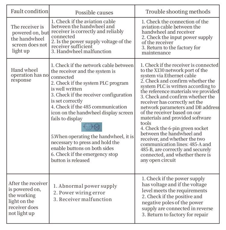
9.Nsogbu A Na-agbapụ
10.Nlekwa anya
1. Biko jiri ya na akọrọ gburugburu ebe obibi na ọnọdụ okpomọkụ na nrụgide ịgbatị ndụ ọrụ ya.
2. Biko zere iji gburugburu ebe obibi dị ka mmiri ozuzo na mmiri mmiri na-agbatị.
3. Biko mee ka ihe dị ọcha dị ọcha ịgbatị ndụ ọrụ ya.
4. Biko zere ịkacha, ida, iferi, wdg. Iji gbochie mmebi nke usoro nkenke n'ime aka ma ọ bụ ezi njehie.
5. Ọ bụrụ na ejighi ya ogologo oge, Biko debe aka na ebe dị ọcha ma dị mma .Nweta nchekwa na njem, A ga-akwụ gị ụgwọ na mmiri na-eguzogide.
11. Ozi Nchedo
1. Biko gụọ ntuziaka ahụ nke ọma tupu iji ya ma gbochie ndị ọkachamara na-abụghị ndị ọrụ.
2. Ọ bụrụ na ọnọdụ ọ bụla na-apụtakarị na aka, Biko kwusi iji ya ozugbo na nsogbu. Tupu nsogbu nchọpụta, Amachibidoro iji aka na-ezighi ezi ọzọ iji zere ihe ọghọm nchekwa nke ihe a na-amaghị ama;
3. Ọ bụrụ na achọrọ mmezi, Biko kpọtụrụ onye nrụpụta. Ọ bụrụ na mmebi nke onwe, Onye na-emepụta ahụ agaghị enye akwụkwọ ikike