Descriptio
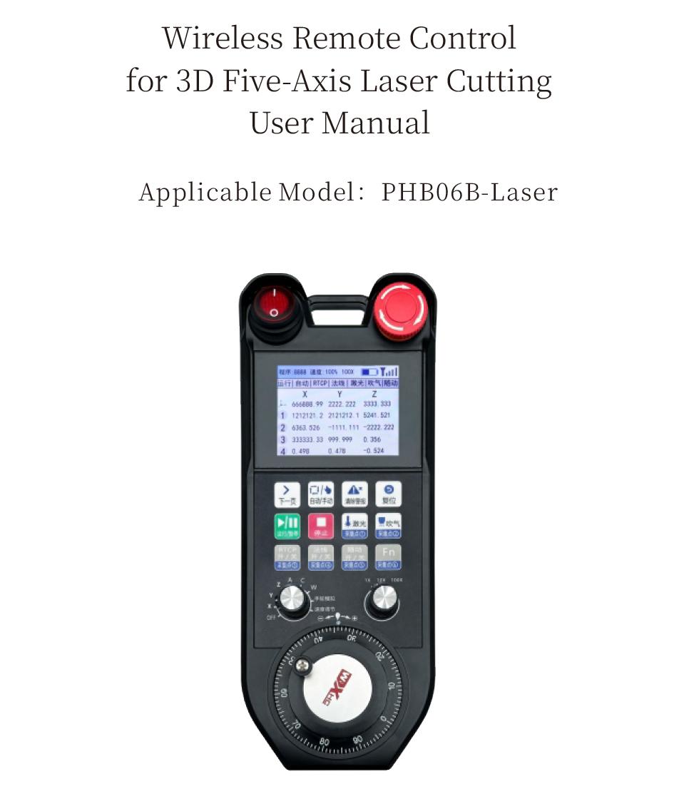
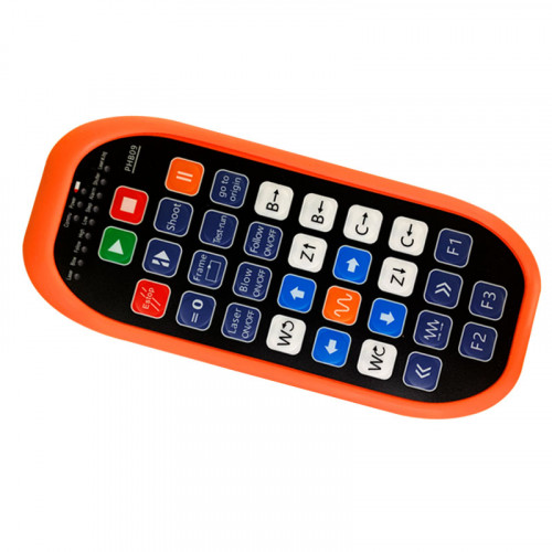
1.Product Introduction
The PHB06B-Laser enables wireless remote control operation of the CNC system via the Modbus TCP protocol, subsidium 12 bullarum, and supports real-time display of system coordinates and status.
2.Product Features
1. 12 bullarum, 6 of which support I/O signals.
2. Supports 2.8-inch color screen display.
3. Supports one 9-level axis selector switch, supporting up to 6-axis output.
4. Supports one 3-level multiplier switch.
5. Supports one electronic remote control, 100 pulses/revolution.
6. Supports receiver Ethernet interface, Modbus TCP communication.
7. Supports standard Type-C charging, 5V-2a præcipiens specificationem, built-in battery specifications 18650/12775mWh.
3.Opus
PHB06B-Laser is connected to the user’s system via an Ethernet interface. It performs data interaction through the Modbus TCP protocol. The user system acts as the Modbus master station, which can transmit real-time system display coordinates and read information such as keys and axis selection of the PHB06B-Laser remote control, so as to realize real-time data communication.
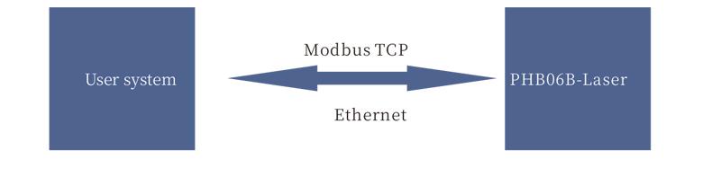
Nota: For the specific protocol, please refer to the “3D 5-axis Laser Cutting – PHB06B – Laser – Modbus Protocol Description”.
4.Product Specifications
| Receptoris potentia copia voltage |
DC5V-DC24V |
| Button lifespan |
1,000,000 temporum |
| Operating Temperature |
-25℃ < X < 55℃
|
| Safe drop height |
1 m |
| Receiver port |
Ethernet |
| Number of buttons |
12
|
| Display screen |
2.8-inch color screen
|
| wireless communication frequency |
433MHz band |
| Receiver sensitivity |
-100dBm
|
| Handheld transmit power |
15dBm
|
| Wireless communicationis spatium |
100 meters barrier-free range |
| Rechargeable Battery Specification |
Rechargeable Battery Specification |
| Charging base power supply voltage |
DC24V/1A |
|
Wired Charging Specification
|
Type-C charging port, DC 5V/2A |
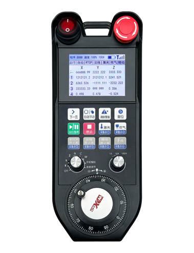
5.Product Function Introduction
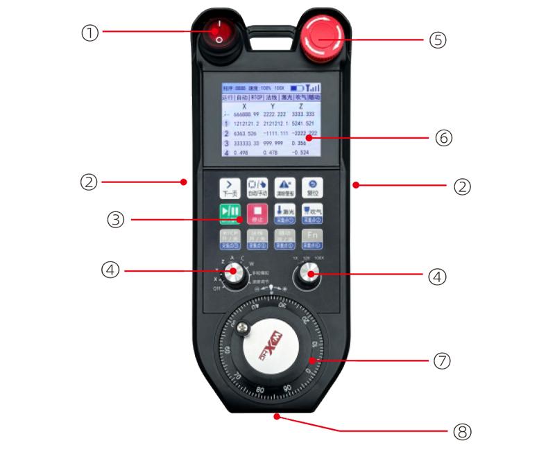
Nota:
① Power Switch
Used to turn the remote control on and off.
② Enable buttons on both sides
The enable button must be pressed while holding the remote control.
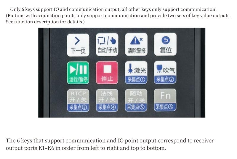
③Button area
12 bullarum
④ Axis Selection and Magnification Switch
One 9-gear axis selection switch; one 3-gear magnification switch.
⑤ Emergency Stop Switch
Remote control emergency stop switch.
⑥ Display Screen Area
It can display coordinates, status and other information.
⑦ Electronic Pulse Encoder
One electronic pulse encoder with 100 pulsus per revolutionem.
⑧ Type-C Charging Port
It is used for connection between the charger and the remote control.
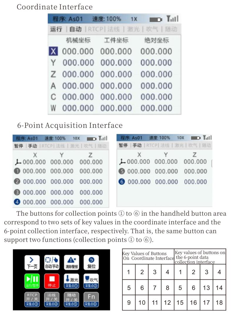
The handheld display includes a coordinate interface and a 6-point acquisition interface, which can be switched by pressing the ‘Next Page’ key
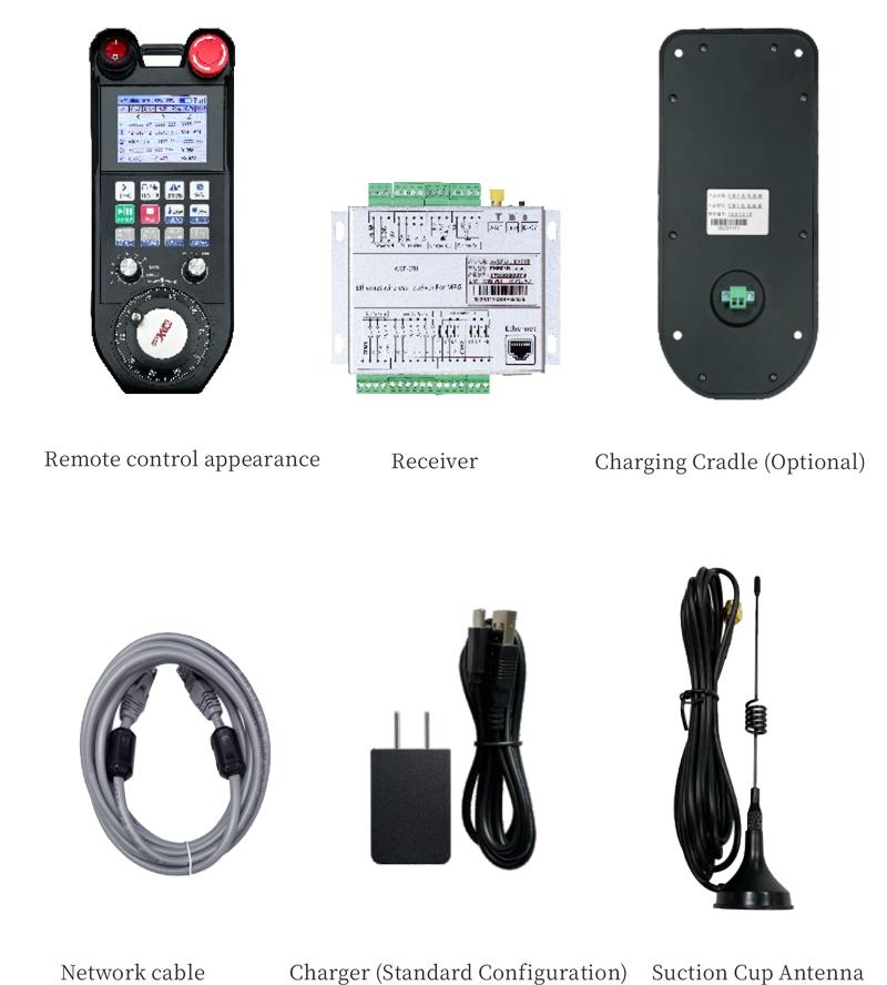
6. Product Accessories Diagram
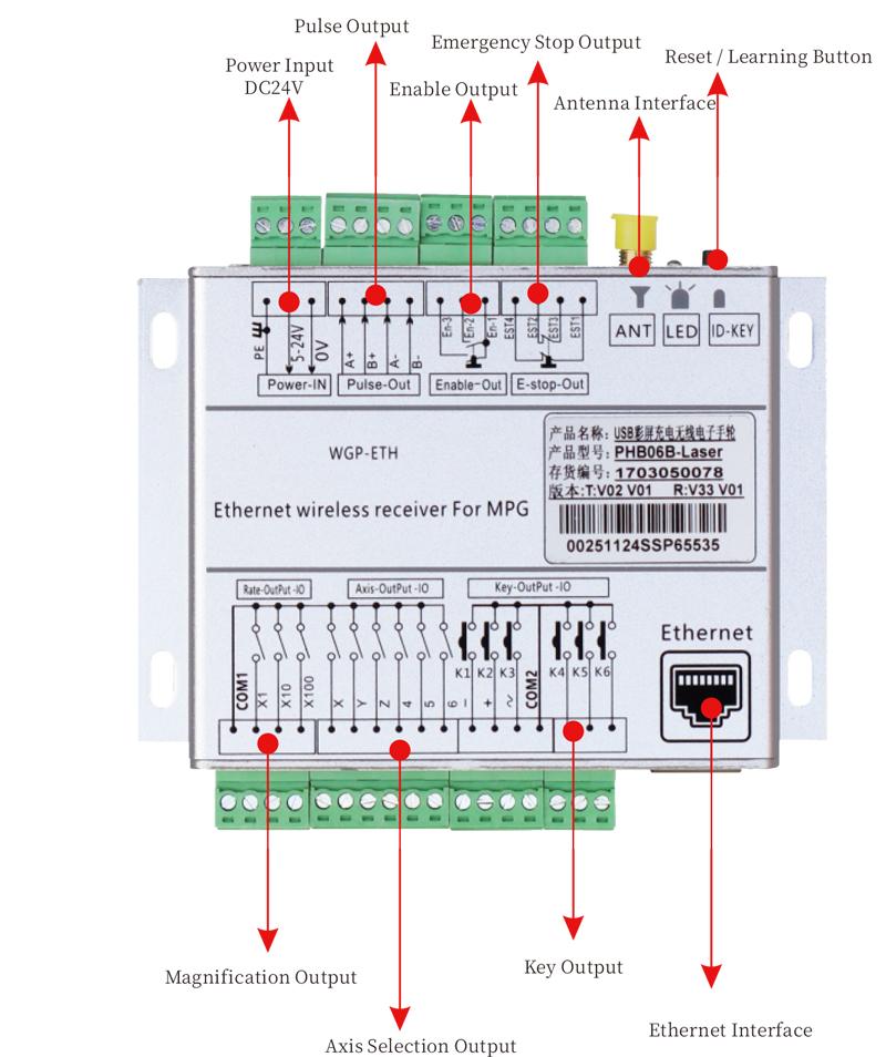
7. Receiver and Wiring Ports
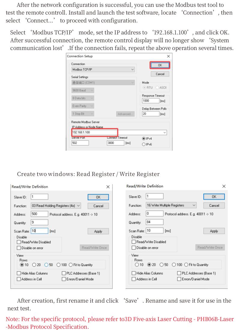
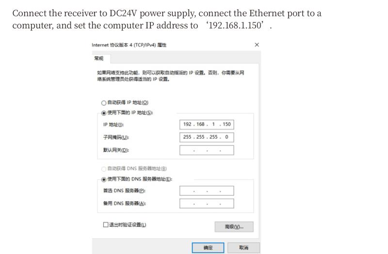
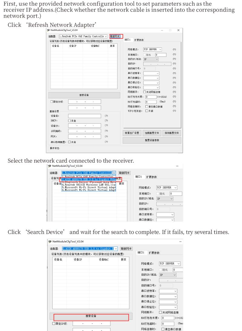
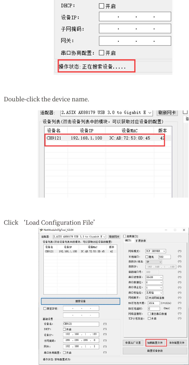
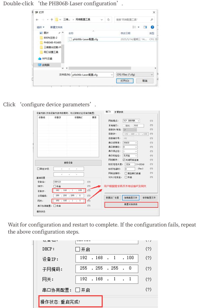
8. Configure network access
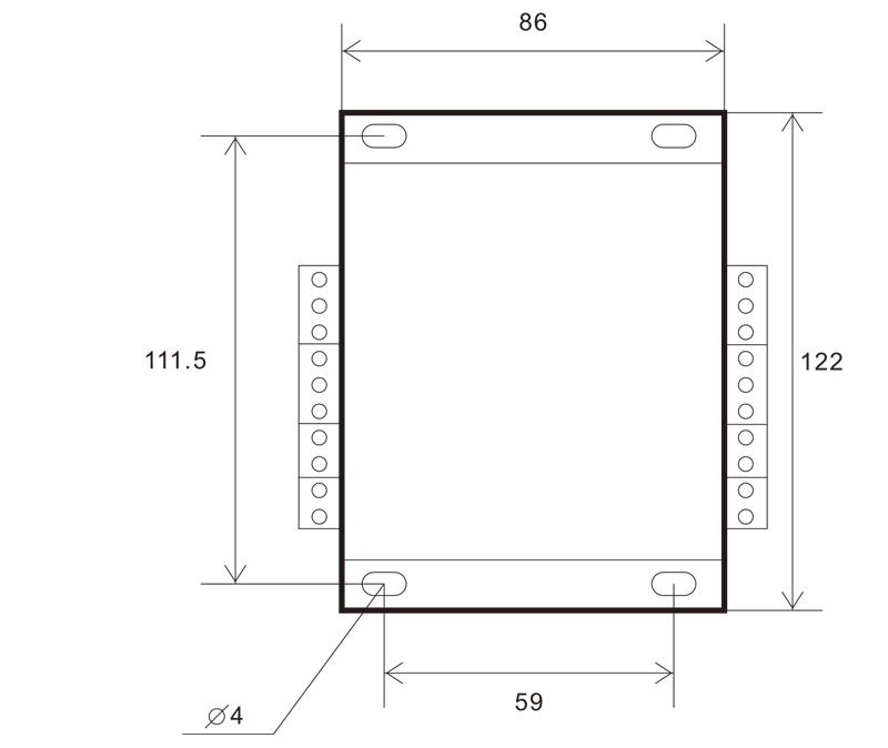
10. Installation dimensions
Receptor installation dimensiones
Unitas: millimeters
Thickness: 29.6mm
 11.Maintenance and upkeep
1. Quaeso uti in sicco environment ad locus temperatus et pressura ad extend ad servitium vitae.
2. Do not use sharp objects to contact the button area to extend button life.
3. Please keep the appearance of the remote control clean to extend its service life.
4. Please avoid crushing, dropping, or bumping, etc.. to prevent damage to the precision components
5. Avoid moisture and shock during storage and transportation.
12.Salus notitia
1. Placere legunt instructiones diligenter ante usum et prohibere non doctorum ex operating.
2. If you repair it yourself and cause damage, the warranty will be void.