Subsidium 2 Fusce Bullae, et switch-type io signum output;
Subsidium -2 axis imperium;
III-campester magnificatio imperium;

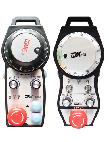
1.Product Introduction
2. Product eget features
| Operans intentione et impetu wireless remote |
3V/14MA
|
| Pugna specifications | 2 AA alcalina batteries, magnitudine 5 |
| Low intentione terror range of wireless remote | < 2.3V |
| Receptoris potentia copia voltage | DC5V-24V/A |
| Receptorem subitis stop output onus range | AC125V-1A/DC30V-2A |
| Receptorem enable range output onus |
AC125V-1A/DC30V-2A
|
| Button receptoris mos output onus range | DC24V/50mA |
| Receptator axis electionis output onus range | DC24V/50mA |
| Receptator magnificationis output onus range | DC24V/50mA |
| Tradere potestatem orci terminalis |
15dBm
|
| Receptoris perceptio sensus | -100dBm |
| Wireless communicationis frequency | 433MHz frequency band |
| Wireless communicationis spatium | Obex liberum spatium 40 metris |
| Operatio temperatus | -25℃ < X < 55℃ |
| Anti ruina altitudo | 1 (meter) |
| Custom button quantitas | 2 |
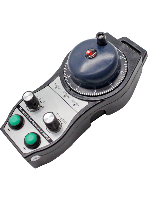
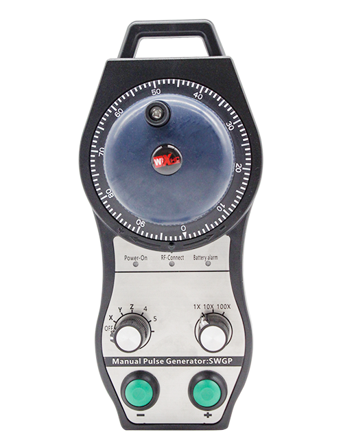
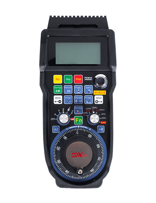
Pulsus encoder:
Torcular et tenere ad activare button, agitabit pulsus encoder, emittunt pulsum signum,et control motus eumdem machinae axis.
Admitte button:
Torcular aut possit puga hinc, et binae efficiat IO outputes in accipiente deducet. Dimittis ad enable puga pyga disiungo ad enable IO output; Et ante axis electionem commutans magnificationem et manus rotam quatiens,ad enable felis eget teneri ad efficax; Hoc munus per configuratione software potest cassari.
Testimonium luminaria:
Lucem sinistram: potentia in lumine,handwheel utitur axis ad eligere ON in potentia, et hoc lumen remanet post potentiam;
Media lux: signum lucis quae illuminat cum operando aliquem functionem eumdem handwheel, et non inluminat, cum nulla operatio est;
Dextra parte lux: Minimum voltage terror lucis, Maximum pugna gradu ",hoc lightflashes vel singulas, altilium debet reponi.
Subitis subsisto puga:
Torcular ad subitis subsisto button, et binos casus necessitatis statur IO outputs in recipiente disiungitur, et omnia functiones handwheel irritae erunt.
Magnificatio switch:
Torcular et tenere ad enable puga mutandae magnificationis switch, quod potest mutare magnificationem moderante handwheel.
Axis lectio switch (Power SWITCH):
Torcular et tenere enable puga mutandae axis lectio transitum, quae motus axis potest flectendum est a handwheel refrenat. Switch hoc switch ab ad axem quemvis et converte in handwheel potestatem.
Custom button:
Duo consuetudo bullarum, inter se correspondentes ad IO output punctum in recipiente.
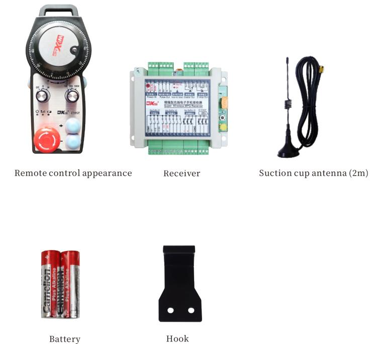
1. Install receptaculum in electricum scrinium per fibula a tergo, vel in scrinium per cochleam in quattuor angulis recipientis niteremur eam.
2. Recipe ad acceptorem wiring diagram et compara cum apparatu tuo on-site. Coniungere apparatu ad accipientis per rudentes.
3.Post accipientem recte certum est, In antenna instructa cum recipientis est connected, et antennae extremum extremum extra electricum scrinium institui vel collocari oportet. Commendatur ponere super summitatem electrica scrinium optimum signum. Prohibetur antennas disiunctas relinquere vel intra electricum scrinium ponere, ut hoc inveniatur in signo inutile.
4. Tandem, conversus in virtute switch ad handwheel, et machina potest operari remote per handwheel.
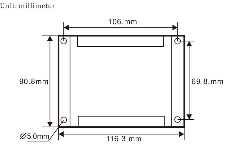
6.2 Receptor installation dimensiones
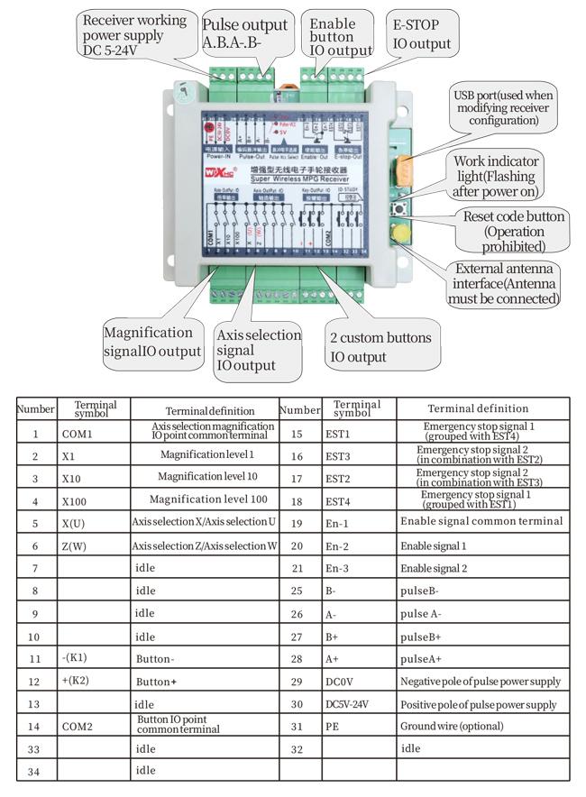
6.3 Receptor Wiring reference Diagram
7. Product Operatio Instructions
1. Potestas in machina et accipientis. Indicatur opus fulgurum lucis accipientis. Install in altilium in in wireless electronic handwheel, ab secure altilium operimentum, et
conversus in virtute switch in wireless electronic handwheel. Gradus machinalis altilium indicator lux est on.
2. Select ad coordinare axem: Torcular et tenere ad activare button, toggle axi delectu transitum, et eligere axis vis operari.
3. Select Magnification: Torcular et tenere ad activare button, magnificationem switch toggle,et eligere desideravit gradu magnificatio.
4. Movens axis: Torcular et tenere ad activare button, Eligere axis selection switch, magnificationem switch eligere, et gyrari pulsus encoder. Gyrari horologico movere
positivi axis et counterclockwise movere axem negativum.
5. Torcular et tenere consuetudinem button, et conjunctionem respondentem IO output recipientis convertetur in. Dimitte puga, et avertit output.
6. Torcular ad subitis subsisto button, IO subitis subitis subsisto in recipientis output disiungitur, munus in handwheel erit erret,subitis subsisto in button dimittere, io subitis subsisto in output claudentur, et munus handwheel restituetur.
7. Nisi handwheel non operatur ad tempus, statim intrabit modus somni ad redigendum potestatem consummatio. Cum autem adhibetur iterum, handwheel potest activated premendo enable button.
8. Nisi handwheel non propter longo tempore, Commendatur ad artem handwheel artem ON situm, Averte Handwheel Power, Et extend ad altilium vitae.
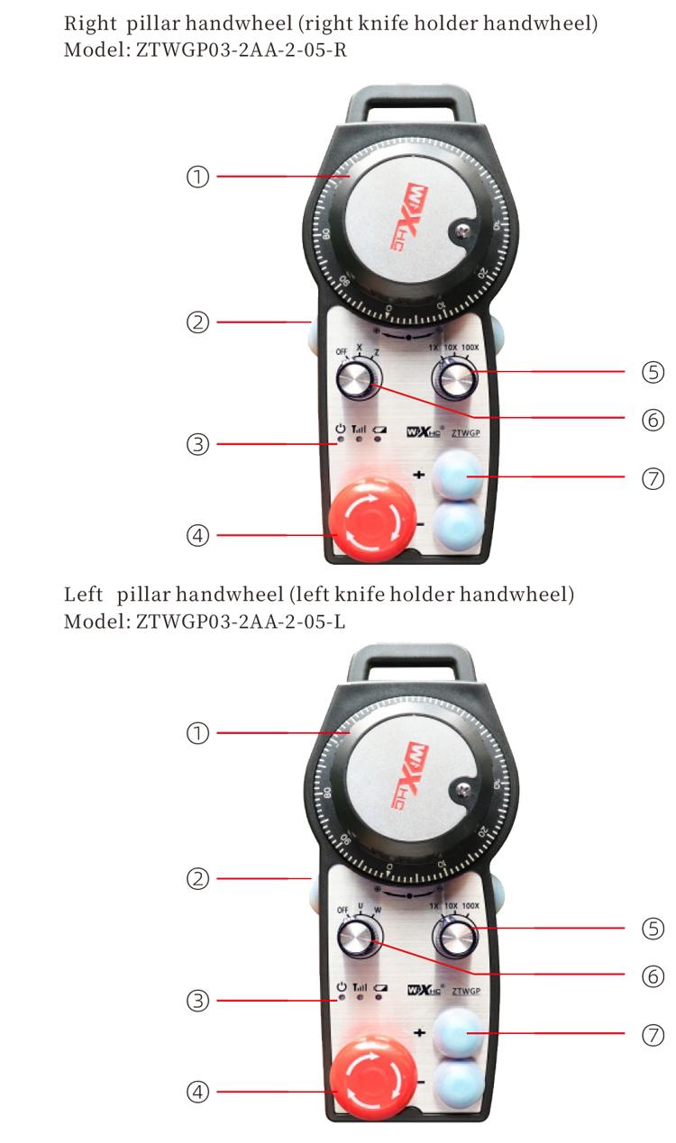
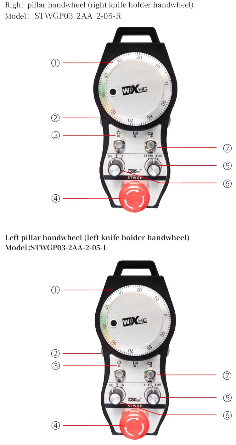
8. Product Model Description

① :ZTWGP significat speciem style
②:Pulsum output parametri:
01: Signum pulsus output indicat esse A, B; Pulsum voltage 5v; cicer quantitas 100PPR.
02:Significans pulsus output signa esse A et B; Pulsus intentione 12V; cicer quantitas 100PPR.
03:Significans pulsus output signa sunt A, B, A -, B -; Pulsum voltage 5v; cicer quantitas 100PPR.
04:Indicat humili gradu NPN aperto Circuit output, et pulsum output annuit de et b;Pulsuum numerus 100PPR . est.
05:Indicat summus gradu PNP Source output, et pulsum output annuit de et b; Pulsuum numerus 100PPR . est.
③:Repraesentat numerum axis delectu virgas, 2 represents 2 secures.
④:Significat genus signo switch axis delectu, Et repraesentat punctum-ut-punctum output signum, et B significat encoded output signo.
⑤:Significat genus multiplicationis switch signum, Et repraesentat punctum-ut-punctum output signum, et B significat encoded output signo.
⑥:Significat numerum consuetudinis globulis, 2 represents 2 Custom Bullae.
⑦:Repraesentat potentiam copiam ad systema handwheel, et 05 Power Repraesentat 5V.
⑧:L significat sinistram columnae (sinistra cultro possessor), et R repraesentat columna dextra (dextra cultro possessor).
9.Solutio ad Product technicorum
1. Quaeso uti in sicco environment ad locus temperatus et pressura ad extend ad servitium vitae.
2. Quaeso vitare usura in abnormes environments talis pluvia et aqua bullae extendere ministerium vitae.
3. Obsecro speciem Handwheel mundus extendat ministerium vitae.
4. Quaeso ne excerpent, procidens, bumping, etc.. ne damnum ad subtilitatem components intra handwheel vel potius errores.
5. Nisi non propter diu, Placere copia handwheel in mundum et tutum est. Per repono et translationem, Operam esse solvit ad humorem et inpulsa resistentia.
11. Salus notitia
1. Placere legunt instructiones diligenter ante usum et prohibere non doctorum ex operating.
2. Quaeso reponere altilium opportune modo cum altilium gradus nimis humilis est ad vitandos errores insufficiens pugna potentia et impotentia operandi handwheel.
3. Si reficere non requiritur, Placere contact fabrica. Nisi damnum est causa sui reparatione, Et manufacturer non providere warantum