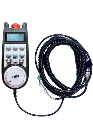
1. Whakamahia he taura waka 6-matua mo te hononga, me te roa o te taura 10 mita.
2. Ka taea e te mata a-ringa te whakaatu i nga mahi a te punaha mahi, Nga whakaurunga miihini,Te reinga whangai, Axis Whiriwhiringa, whakanui, me etahi atu korero.
3. Tautoko Peke Kore Tautoko, hurihuri io tohu tohu, a ko te wa ohorere o te ringaringa he tika tonu.
4. Tautoko 6 pātene ritenga, Whakawhiti i nga tohu IO, a ka taea e nga tohu whakaputa ki te punaha ma te waea, whakawhitiwhiti korero ranei.
He pukapuka tohutohu a-ringa hiko
Whakaaturanga
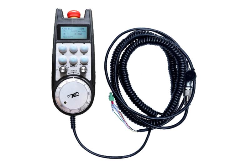
1. Kupu whakataki
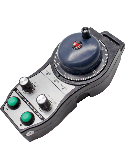
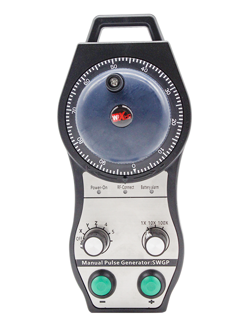
Ka whakamahia te ringaringa hiko mo te aratohu ā-ringa, tūranga, Ko te whakahāngai taputapu, me etahi atu mahi i runga i nga taputapu miihini CNC. Ko tenei tauira o te ringaringa hiko he siemens whakaatu tonu i nga whakaaturanga hiko elechonic. Ka hono te ringaringa ki te atanga X130 o te punaha Siemens ma te taura whatunga, Na ko nga whakaurunga punaha ka panuihia, ka whakaatuhia ki te mata LCD o te ringaringa ma te whakawhitiwhiti korero S7. Ka taea hoki e te ringaringa te whakahaere i te kowhiringa a Axis, whakanui, pātene, Ko nga tohu me nga tohu a taiao ma te whakawhitiwhiti korero.
2.Nga waahanga mahi hua
1. Whakamahia he taura waka 6-matua mo te hononga, me te roa o te taura 10 mita.
2. Ka taea e te mata a-ringa te whakaatu i nga mahi a te punaha mahi, Nga whakaurunga miihini,Te reinga whangai, Axis Whiriwhiringa, whakanui, me etahi atu korero.
3. Tautoko Peke Kore Tautoko, hurihuri io tohu tohu, a ko te wa ohorere o te ringaringa he tika tonu.
4. Tautoko 6 pātene ritenga, Whakawhiti i nga tohu IO, a ka taea e nga tohu whakaputa ki te punaha ma te waea, whakawhitiwhiti korero ranei.
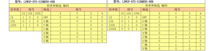
5. Tautoko 6 rānei 8 Te whakahaere Axis, me nga tohu whakawhiti io ka taea te whakaputa ki te punaha ma te waea, i te whakawhitiwhiti korero ranei.
6. Tautoko 3 rānei 4 Nga taumata o te mana whakanui, me nga tohu whakawhiti io ka taea te whakaputa ki te punaha ma te waea, i te whakawhitiwhiti korero ranei.
7. Tautokohia te whakauru a Pulse, 100 Pulses / Tahuri, Ka taea e nga tohu whakaputa ki te punaha ma te AB Pulse Haring.
8. Ka tautokohia nga kawa S7 me nga Siemens 828D, 840DSL, Tetahi me etahi atu punaha tauira.
3. Whakatakotoranga Hua
| Te Mahi Toha Whakawhiwhi Mahi Handwheel | DC24V / 1A |
| Kaituku Tohunga Kaitiaki Mana | DC24V / 1A |
| Kaiwhakaputa Io Putanga Utu | DC24V |
| Te roa o te wira e mutu ana te roa | 10m |
| Te roa o te kaiwhiwhi mutunga | 1m |
| Te roa o te kaiwhiwhi | 3m |
| Pāmahana whakahaere | -25℃<Whakaahua x<55℃ |
| Te teitei anti-hinga | 1m |
| Te rahinga pātene Ritenga | 6 |
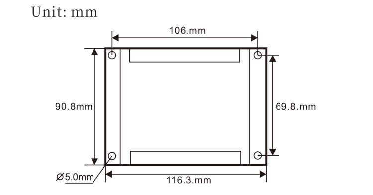
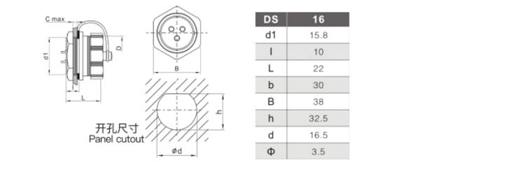
| Nga Taumata Hua | 233*90.7*77.4(Mm) |
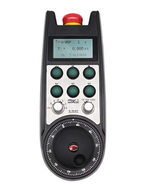
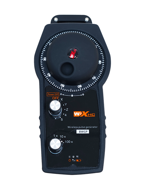
4.He kupu whakataki hua
Rangi:
Pātene aukati ohorere:
Pēhi i te pātene aukati ohorere, me nga huinga e rua o te wa ohorere o te aukati io i te kaiwhiwhi ka whakakorehia, me nga mahi katoa o te ringaringa ka kore e tika.
I muri i te tuku i te aukati ohorere, Ko te aukati ohorere i te putanga o te kaiwhiwhi i runga i te kaiwhiwhi kua kati, me nga mahi katoa o te ringaringa kua whakahokia mai.
whakaaturanga mata:
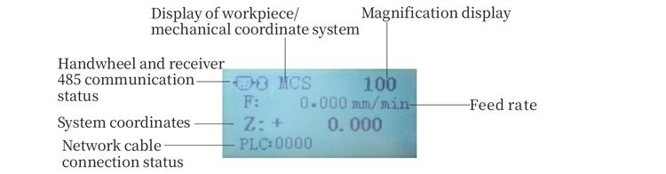
Pc: 0000 e whakaatu ana kaore i te hono te taura whatunga, Pc: 1010 E whakaatu ana ko te taura whatunga he pai te hono atu ki te punaha PLC.
Pc: 1110 tohu angitu te tuhi angitu o nga raraunga punaha ki te ringaringa, Pc: 0001 He tohu angitu ki te rorohiko.
③ pātene ritenga:
6 pātene ritenga, ia tangata e hāngai ana ki te wāhi putanga IO ki te kaiwhiwhi, hono hoki ki te punaha ma te whakawhitiwhiti korero.
te huringa whiriwhiri:
Ka taea e te huringa tohu toki te huri i te toki nekehanga i whakahaerehia e te ringaringa.
⑤ Whakahohe pātene:
Press me te pupuri i te paatene i nga taha e rua ki te whakahohe i te kaimau Pulse ma te wiri. A ko nga roopu e rua i runga i te kaiwhiwhi e taea ai te whakaputa ki te whakahaere, Tukuna te pātene Whakahohe kia taea ai e te Io putanga ki te hono.
te whakawhiti whakanui:Ka taea e te huringa whakanui te huri i te whakanui
e whakahaerehia ana e te ringaringa.
te whakauru a Pulse:
Pēhi me te pupuri i te pātene Whakahohe, Wiri i te kaimau pulse, Te whakaputa i tetahi tohu Pulse, me te whakahaere i te nekehanga o te neke miihini.
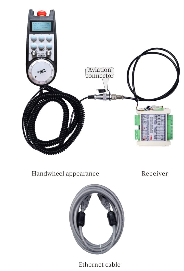
⑧ Cable Handwheel:
Ka taea te hono atu i te ringaringa me te kaiwhiwhi, plug aviation, whakamahia mo te tuku hiko me te whakawhitiwhiti korero.
5. Whakaahua Whakauru Hua
6. Aratohu Whakauru Hua
6.1 Tikanga whakaurunga Hua
6.1 Tikanga whakaurunga Hua
1. Tāutahia te kaiwhiwhi ki te rūnanga hiko na roto i nga kohinga whiu i nga kokonga e wha.
2. Tirohia ki to maatau kaiwhiwhi i te hoahoa me te whakataurite i o taputapu taputapu-a-papa. Whakauruhia te taputapu ki te kaiwhiwhi ma te taura me te hono i te kaiwhiwhi ki te atanga x130 o te punaha ma te whakamahi i nga taura Ethernet.
3. I muri i te whakatika i te kaiwhiwhi, Tāutahia te papa rererangi i te waahi whakatuwheratanga o te ringaringa ki te Paewhiri, ka hono atu ki tetahi atu pito o te turanga ki te atanga a-ringa i runga i te kaiwhiwhi. Na ka whakauru i te plug Aviation o te taura ringaringa ki roto i te turanga me te whakakii i te taputapu whakatika.
6.2 Nga Taumata Whakauru
6.3 Nga Taumata Whakauru o nga Momo Aviation
6.4 He hoahoa tohutoro a te kaiwhiwhi
 7.Tohutohu Mahi Hua
7.Tohutohu Mahi Hua
1. Ka whakahaerehia te kaiwhiwhi me te tohu tohu e tohu ana i te kaiwhiwhi, Whakauruhia te kaiwhiwhi ki te rorohiko me te taura whatunga, Whakatauhia te wahitau IP kua whakaritea mo te rorohiko, me te whakamahi i nga punaha taputapu whirihoranga whatunga hei whakarite i nga tohu o te whatunga o te mahi a-ringa. Mo nga tikanga tautuhi motuhake, Tirohia te “LXWGP-ETS I WHAKAMAHI I TE WHAKAMAHI I TE WHAKAMAHI I TE WHAKAMAHI”.
2.I muri i te whakatuunga te kaiwhiwhi, Me whai te punaha i te hotaka PLC. Tena tirohia te “LXWGG-ETS He rereke nga punaha whakahaere i nga punaha whakahaere” me nga rauemi a PC PLC mo nga korero taipitopito.
3.I muri i te whakaoti i nga tautuhinga i runga ake nei, Tangohia te kaiwhiwhi ki te rūnanga hiko miihini me te whakauru i te reira. Tangohia te taura whatunga mai i te rorohiko ka hono atu ki te atanga X130 o te punaha.Connect te kaituku mana me te raina relse.3.
4.I muri i te whakaoti i nga tautuhinga i runga ake nei, Tangohia te kaiwhiwhi ki te rūnanga hiko miihini me te whakauru i te reira. Tangohia te taura whatunga mai i te rorohiko ka hono atu ki roto i te atanga x o te punaha. Tūhono te kaiwhiwhi mana me te raina perehana.
5. Tīpakohia te Whiringa Axis: Hurihia te huringa o te toki ka kowhiri i te toki e hiahia ana koe ki te whakahaere i runga.
6. Tīkina te whakanui: Hurihia te huringa whakanui me te whiriwhiri i te taumata whakanui e hiahia ana koe.
7. Neke toki: Pēhi me te pupuri i te pātene Whakahohe, Tīpakohia te huringa whiriwhiri Axis, Tīpakohia te whakawhiti whakanui, Na ka hurihia te kaikohi Pulse ki te huri i te toki neke pai i te karaka me te neke atu i te toki i te neke.
8. Press me te pupuri i tetahi paatene ritenga kia huri i te putanga o te IO o te paatene i te kaiwhiwhi, ka tukuna te pihi hei whakaweto i te putanga.
9. Pēhi i te pātene aukati ohorere, Ko te aukati i te aukati i te whakaputanga o te kaiwhiwhi ka whakakorehia, Ka monokia te mahi a-ringa, Tukuna te pātene aukati ohorere, Ka kati te putanga ohorere io, Na ka whakahokia mai te mahi a-ringa.
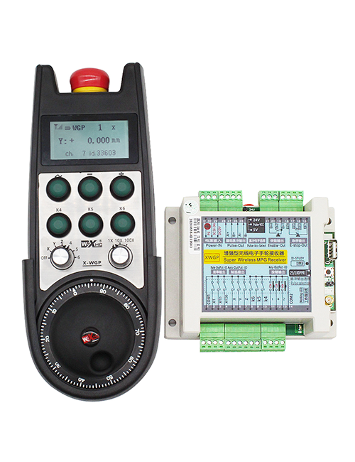
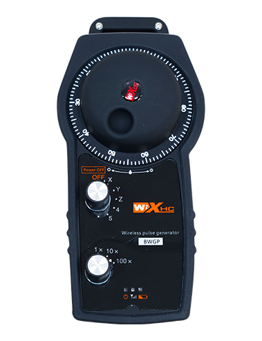
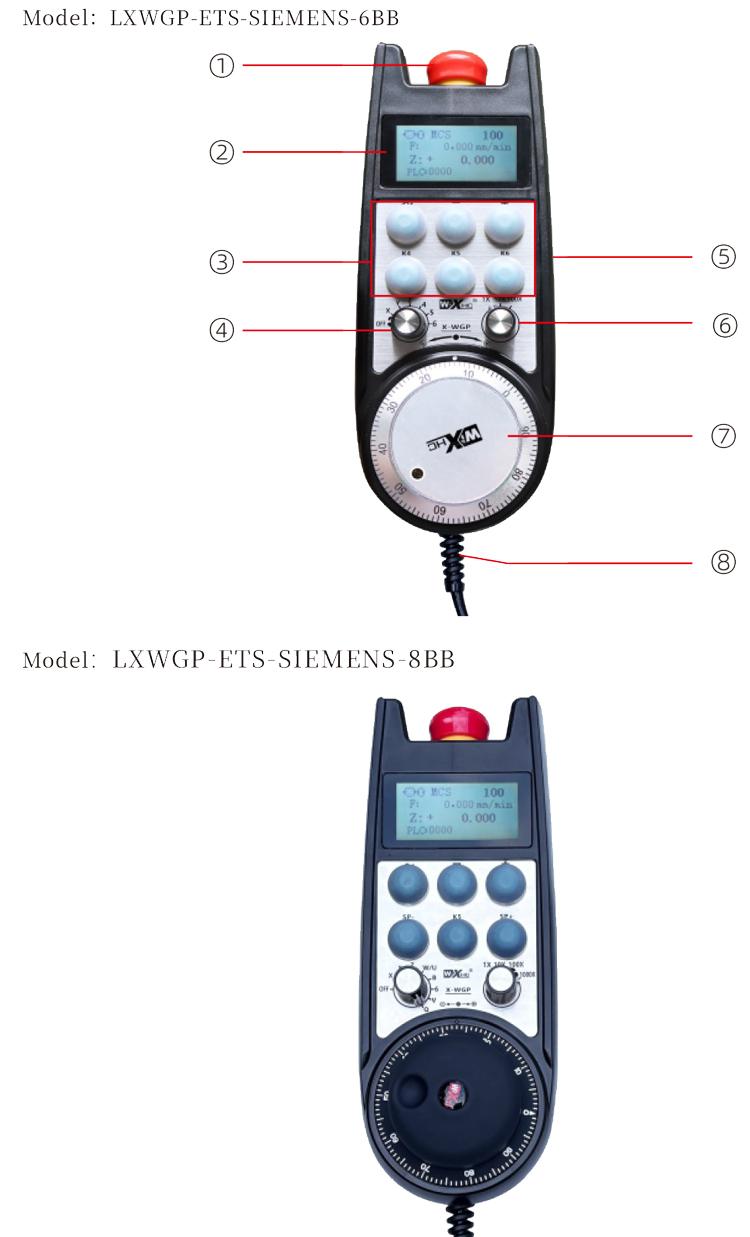
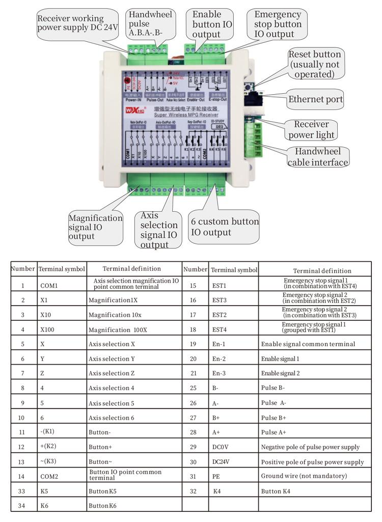
8.Whakaahuatanga Tauira Hua

① LXWGP e tohu ana i te ahua ahua pai, me te atanga whakawhitiwhiti korero a te kaiwhiwhi
He atanga ethernet.
② : Tohu mo te punaha Siemens motuhake.
③ : tohu te maha o nga huringa whiriwhiri Axis, tohu nga toki, me te tohu
oka.
④ : tohu te momo tohu o te Axis me te tohu whakanui, He tohu
tohu tohu-ki-tohu tohu, me te B e tohu ana i te tohu whakauru whakauru.
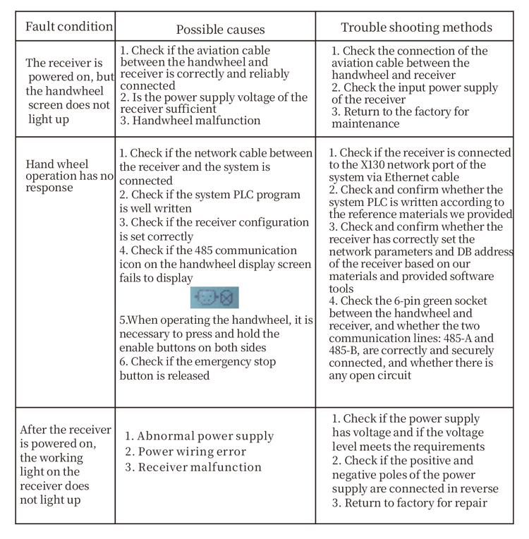
9.He pupuhi raru hua
10.Whakatikatika
1. Whakamahia koa ki te taiao maroke i te pāmahana o te rūma me te pehanga kia whakawhānuitia tana mahi ratonga.
2. Tena ra, kaua e whakamahia te whakamahi i nga taiao kore penei i te ua me nga mirumiru wai hei whakawhānui i te koiora ratonga.
3. Kia mau ki te ahua o te ringaringa ma te horoi ki te whakawhānui i tana mahi ratonga.
4. Tena koa karohia te kotiti, hinga, tōpito, take. Hei aukati i te kino o nga waahanga tika i roto i te ringaringa, i nga hapa tika ranei.
5. Mena kaore i whakamahia mo te wa roa, Tēnā Toa koa te ringaringa ki te waahi ma me te haumaru.During rokiroki me te kawe waka, Me utu te aro ki te makuku me te aukati i te aukati.
11. Nga korero mo te Haumaru
1. Tena panuihia nga tohutohu i mua i te whakamahi me te aukati i nga umanga kore ngaio mai i te mahi.
2. Mena he ahuatanga noa te ahuatanga o te ringaringa, Whakamutua te whakamahi i te waa tonu me te raru. Tuhinga o mua, Ka rukuhia kia whakamahia ano e ia te ringaringa he ki te karo i nga aitua mo te haumaru i puta mai i nga hapa a-ringa kaore e mohiotia ana;
3. Mena e hiahiatia ana te whakatikatika, Tena whakapā atu ki te kaiwhakanao. Mena he kino te kino na te whakatikatika i a ia ano, Kaore te kaiwhakanao e tuku raihana