Supports 2 customizable buttons, with switch-type IO signal output;
Supports -2 axis control;
Supports 3-level magnification control;

1.Nthuts'i ñut'i producto
2. Características funcionales ar producto
| Operating voltage and current of wireless remote |
3V/14MA
|
| Battery specifications | 2 AA alkaline batteries, size 5 |
| Low voltage alarm range of wireless remote | < 2.3V |
| Voltaje fuente alimentación ar receptor | DC5V-24V/A |
| Receiver emergency stop output load range | AC125V-1A/DC30V-2A |
| Receiver enable output load range |
AC125V-1A/DC30V-2A
|
| Receiver custom button output load range | DC24V/50mA |
| Receiver axis selection output load range | DC24V/50mA |
| Receiver magnification output load range | DC24V/50mA |
| Nts'edi transmisión terminal 'ye̲ |
15dBm
|
| Receptor recibiendo sensibilidad | -100dBm |
| Frecuencia comunicación inalámbrica | 433'me̲i frecuencia MHz |
| Distancia comunicación inalámbrica | Mbi mpe̲fi barreras 40 meters |
| Mpat'i funcionamiento | -25° c < X < 55° c |
| altura resistencia caída | 1 (meter) |
| Yá 'bede ya botón personalizado | 2 |

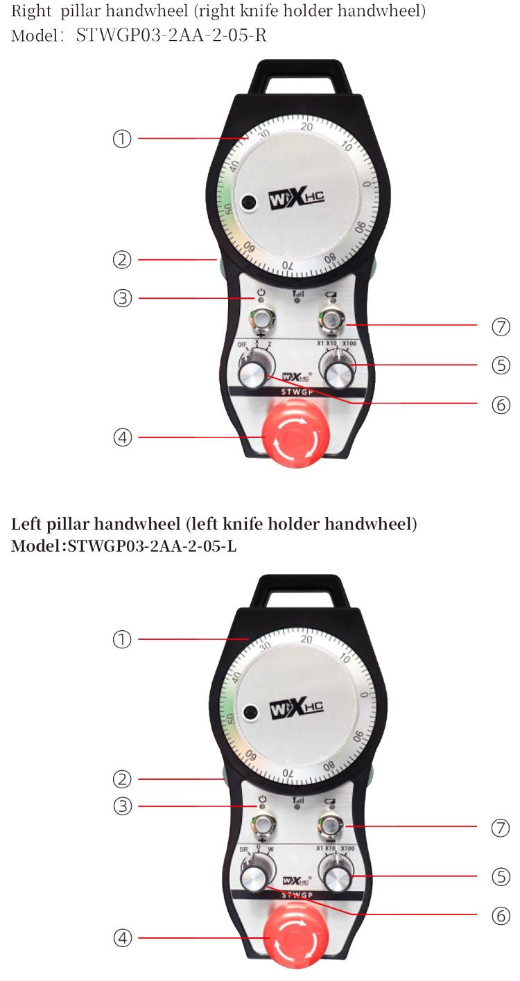
(1) codificador pulso:
Presione ne mantenga pulsado ar botón habilitar, agitar codificador pulso, emitir 'nar señal pulso,ne controlar yá 'ñäni eje ar máquina.
(2) botón ar activar:
Pulse 'na botón habilitar jar 'na ngehnu̲, ne yoho ya conjuntos ya salidas habilitar IO ja ar receptor conducirá. Suelte botón habilitar pa desconectar ar salida habilitar IO; 'be̲tho mpa̲ti ar aumento selección ejes ne girar ar volante,botón habilitar da zeti ar abajo pa da xi hño; Nuna ar función to da desactivada a través de software configuración.
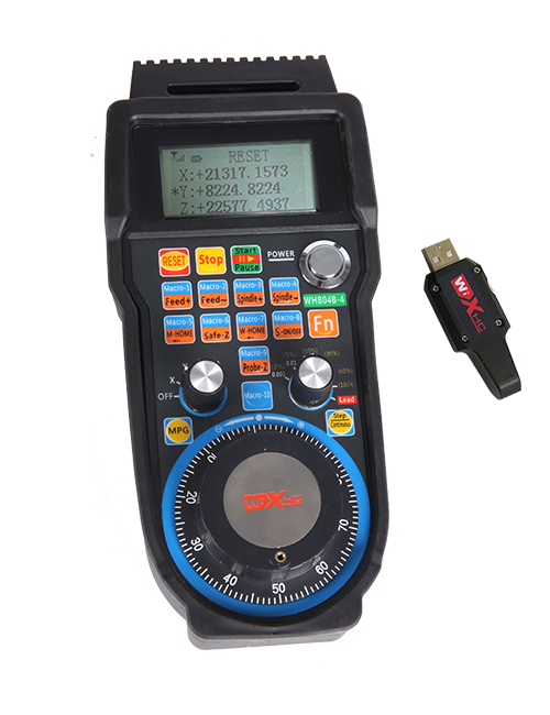
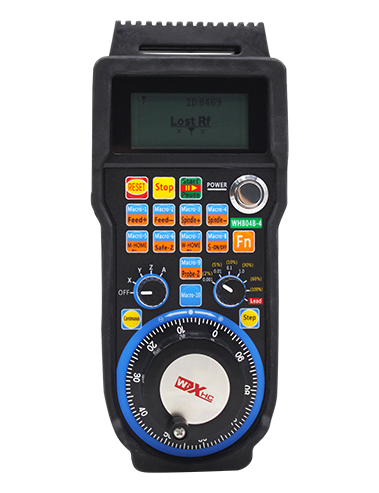
(3) ya indicadoras:
Left side light: power on light,the handwheel uses the axis to select OFF for power on, and this light stays on after power on;
Middle light: a signal light that lights up when operating any function ofthe handwheel, and does not light up when there is no operation;
Right side light: Low voltage alarm light, low battery level,this lightflashes or stays on, battery needs to be replaced.
④ Emergency stop button:
Press the emergency stop button, yoho ya conjuntos salidas IO parada emergencia ja ar receptor ar desconectarán, ga̲tho ya 'befi ar volante ar desactivarán.
⑤ Magnification switch:
Press and hold the enable button to switch the magnification switch, nä'ä to mpa̲ti ar aumento ajustado ir nge ar volante.
(6) interruptor selección eje (interruptor encendido):
Presione ne mantenga presionado botón habilitar pa mpa̲ti interruptor selección eje, nä'ä to mpa̲ti eje yá 'ñäni controlado ir nge ar volante. Gire nuna interruptor OFF ma 'na eje ne encienda ar energía ar volante.
(7) botón personalizado:
Yoho botones personalizados, kadu 'na vinculado ja 'nar punto salida IO ja ar receptor.
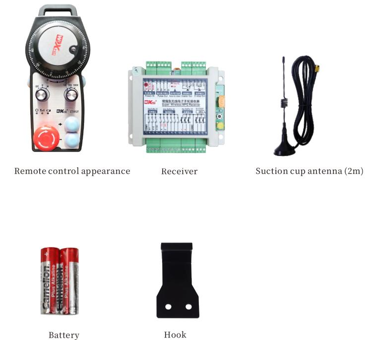
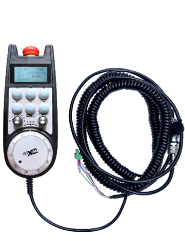
1. Instalar ar receptor ar armario eléctrico utilizando ar hebilla trasera, wa asegurar nä'ä ja ar gabinete ir nge ya tornillos ja ya goho esquinas ar receptor.
2. Consulte ma diagrama cableado receptor ne comparar ko ár configuración jar sitio. Conecte ar equipo ja ar receptor ir nge ya cables.
3.Después ja da ar receptor xi montado makwäni, the antenna equipped with the receiver must be connected, and the outer end of the antenna should be installed or placed outside the electrical cabinet. It is recommended to place it on the top of the electrical cabinet for the best signal effect. It is prohibited to leave the antenna unconnected or place it inside the electrical cabinet, as this may result in the signal being unusable.
4. Finally, turn on the power switch of the handwheel, and you can operate the machine remotely using the handwheel.
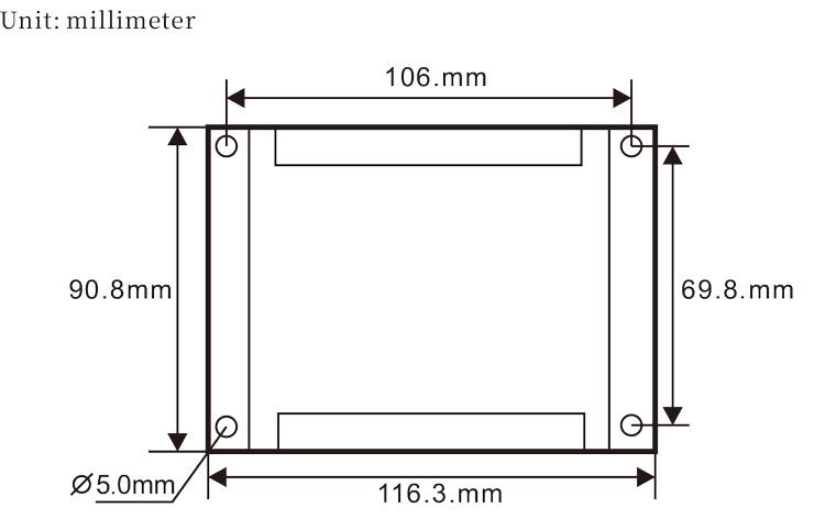
6.2 Receiver installation dimensions
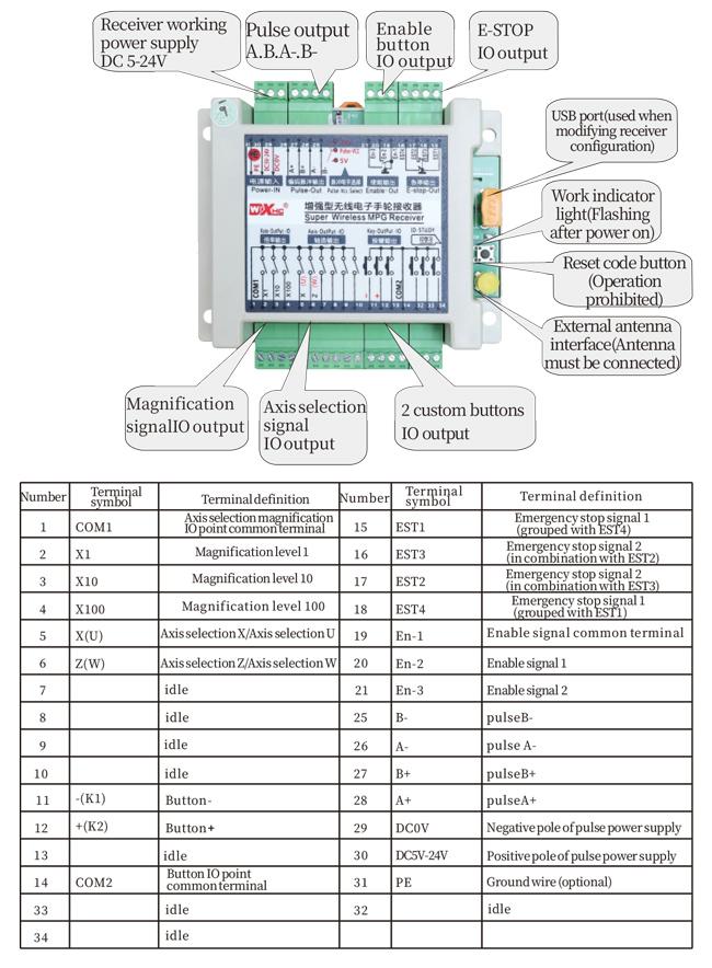
6.3 Receiver Wiring Reference Diagram
7. Product operation instructions
1. Power on the machine and the receiver. The receiver’s working indicator light flashes. Install the battery in the wireless electronic handwheel, secure the battery cover, and
turn on the power switch of the wireless electronic handwheel. The handwheel’s battery level indicator light is on.
2. Select the coordinate axis: Presione ne mantenga pulsado ar botón habilitar, toggle the axis selection switch, and select the axis you want to operate.
3. Select magnification: Presione ne mantenga pulsado ar botón habilitar, toggle the magnification switch,and select the desired magnification level.
4. Eje móvil: Presione ne mantenga pulsado ar botón habilitar, select the axis selection switch, select the magnification switch, and then rotate the pulse encoder. Rotate clockwise to move the
positive axis and counterclockwise to move the negative axis.
5. Press and hold any custom button, and the corresponding button IO output of the receiver will be turned on. Release the button, and the output will be turned off.
6. Press the emergency stop button, the corresponding emergency stop IO output of the receiver will be disconnected, the handwheel function will be disabled,release the emergency stop button, the emergency stop IO output will be closed, and the handwheel function will be restored.
7. If the handwheel is not operated for a period of time, it will automatically enter sleep mode to reduce power consumption. When it is used again, the handwheel can be activated by pressing the enable button.
8. If the handwheel is not used for a long time, it is recommended to switch the handwheel shaft to the OFF position, turn off the handwheel power, and extend the battery life.
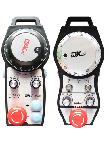
8. Product Model Description

① :ZTWGP represents the appearance style
②:Pulse output parameters:
01: Indicates that the pulse output signal is A, B; Pulse voltage 5V; pulse quantity 100PPR.
02:Indicating thatthe pulse output signals are A and B; Pulse voltage 12V; pulse quantity 100PPR.
03:Indicating thatthe pulse output signals are A, B, A -, B -; Pulse voltage 5V; pulse quantity 100PPR.
04:Indicates a low-level NPN open circuit output, with pulse output signals of A and B;The number of pulses is 100PPR.
05:Indicates high-level PNP source output, with pulse output signals of A and B; The number of pulses is 100PPR.
③:Representing the number of axis selection switches, 2 represents 2 axes.
④:Represents the type of axis selection switch signal, A represents point-to-point output signal, and B represents encoded output signal.
⑤:Represents the type of multiplication switch signal, A represents point-to-point output signal, and B represents encoded output signal.
⑥:Represents the number of custom buttons, 2 represents 2 custom buttons.
⑦:Represents the power supply for the system handwheel, and 05 represents 5V power supply.
⑧:L represents the left column (left knife holder), and R represents the right column (right knife holder).
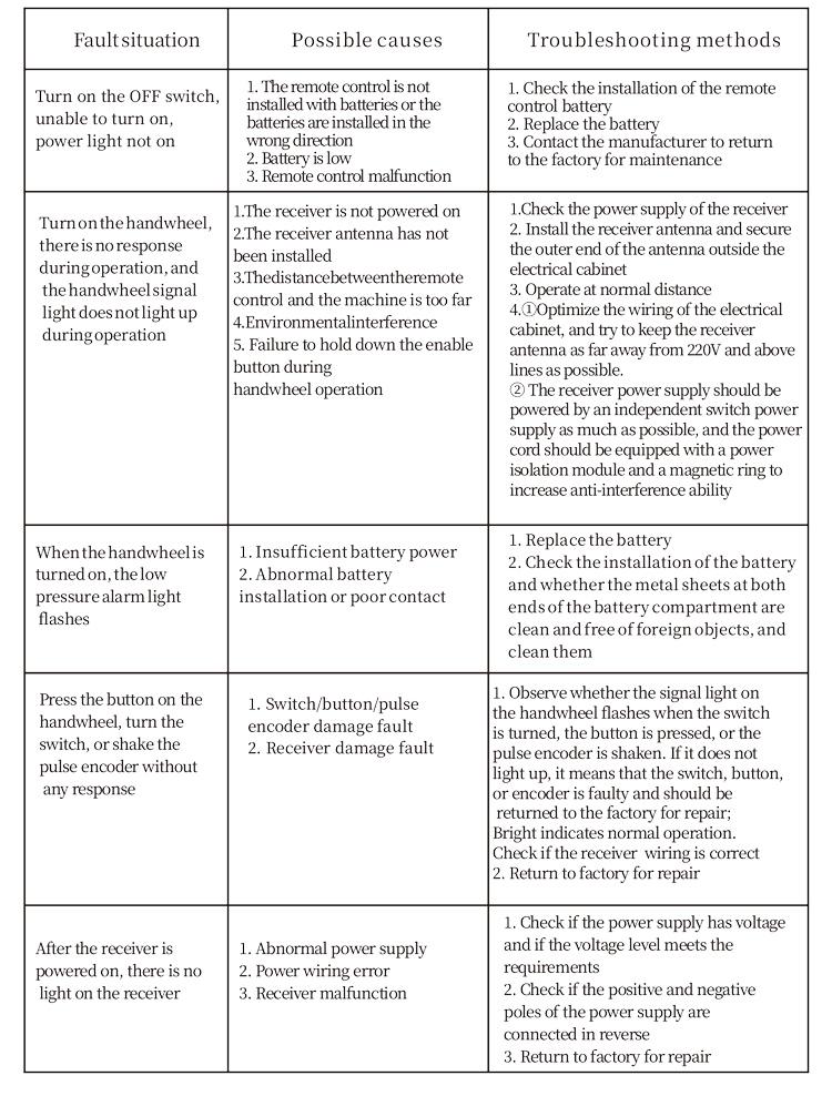
9.Solution to Product Malfunctions
1. Please use it in a dry environment at room temperature and pressure to extend its service life.
2. Please avoid using in abnormal environments such as rain and water bubbles to extend the service life.
3. Please keep the appearance of the handwheel clean to extend its service life.
4. Please avoid squeezing, falling, bumping, etc.. to prevent damage to the precision components inside the handwheel or accuracy errors.
5. If not used for a long time, please store the handwheel in a clean and safe place. During storage and transportation, attention should be paid to moisture and shock resistance.
11. Safety Information
1. Please read the instructions carefully before use and prohibit non professionals from operating.
2. Please replace the battery in a timely manner when the battery level is too low to avoid errors caused by insufficient battery power and inability to operate the handwheel.
3. If repair is required, please contact the manufacturer. If the damage is caused by self repair, the manufacturer will not provide warranty