Obsługuje 2 konfigurowalne przyciski, z wyjściem sygnału IO typu przełącznikowego;
Obsługuje -2 kontrola osi;
Obsługuje 3-stopniową kontrolę powiększenia;

1.Wprowadzenie produktu
2. Cechy funkcjonalne produktu
| Napięcie robocze i prąd pilota bezprzewodowego |
3V/14MA
|
| Specyfikacje baterii | 2 Baterie alkaliczne AA, rozmiar 5 |
| Zakres alarmu niskiego napięcia pilota bezprzewodowego | < 2.3V |
| Napięcie zasilania odbiornika | DC5V-24V/A |
| Zakres obciążenia wyjściowego zatrzymania awaryjnego odbiornika | AC125V-1A/DC30V-2A |
| Odbiornik umożliwia zakres obciążenia wyjściowego |
AC125V-1A/DC30V-2A
|
| Niestandardowy zakres obciążenia wyjściowego przycisku odbiornika | DC24V/50mA |
| Zakres obciążenia wyjściowego wyboru osi odbiornika | DC24V/50mA |
| Zakres obciążenia wyjściowego powiększenia odbiornika | DC24V/50mA |
| Moc transmisji terminala ręcznego |
15dBm
|
| Czułość odbioru odbiornika | -100dBm |
| Częstotliwość komunikacji bezprzewodowej | 433pasmo częstotliwości MHz |
| Odległość komunikacji bezprzewodowej | Odległość bez barier 40 metry |
| Temperatura pracy | -25℃ < X < 55℃ |
| Wysokość zapobiegająca upadkowi | 1 (metr) |
| Niestandardowa ilość przycisków | 2 |

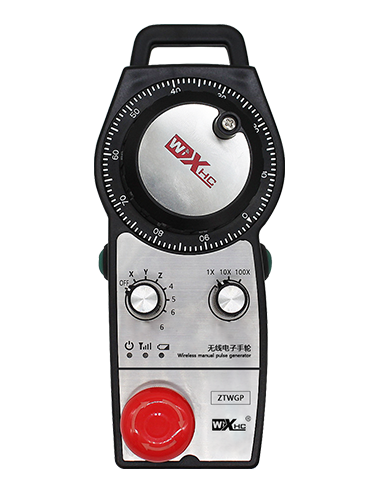
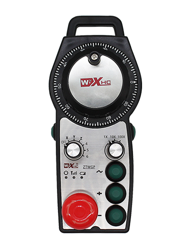
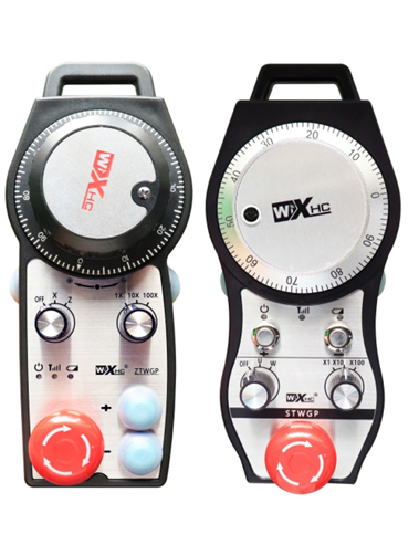
① Enkoder impulsowy:
Naciśnij i przytrzymaj przycisk włączania, potrząśnij enkoderem impulsowym, emitują sygnał impulsowy,i sterować ruchem osi maszyny.
② Przycisk Włącz:
Naciśnij dowolny przycisk włączania po dowolnej stronie, oraz dwa zestawy wyjść włączających IO na odbiorniku będą przewodzić. Zwolnij przycisk włączania, aby odłączyć włączone wyjście IO; A przed przełączeniem powiększenia wyboru osi i potrząśnięciem kołem zamachowym,Aby funkcja działała, przycisk włączania musi być przytrzymywany; Funkcję tę można anulować za pomocą oprogramowania konfiguracyjnego.
③ Kontrolki:
Lewe światło boczne: włącz światło,pokrętło wykorzystuje oś do wybrania WYŁ. w celu włączenia zasilania, i ta kontrolka pozostaje zapalona po włączeniu zasilania;
Światło średnie: lampka sygnalizacyjna, która zapala się podczas obsługi dowolnej funkcji pokrętła, i nie świeci się, gdy nie jest wykonywana żadna operacja;
Światło boczne prawe: Światło alarmowe niskiego napięcia, niski poziom baterii,ta kontrolka miga lub pozostaje włączona, bateria wymaga wymiany.
④ Przycisk zatrzymania awaryjnego:
Naciśnij przycisk zatrzymania awaryjnego, a dwa zestawy wyjść IO zatrzymania awaryjnego w odbiorniku zostaną odłączone, i wszystkie funkcje pokrętła będą nieaktywne.
⑤ Przełącznik powiększenia:
Naciśnij i przytrzymaj przycisk włączania, aby przełączyć przełącznik powiększenia, który może przełączać powiększenie kontrolowane za pomocą pokrętła.
⑥ Przełącznik wyboru osi (wyłącznik zasilania):
Naciśnij i przytrzymaj przycisk włączania, aby przełączyć przełącznik wyboru osi, który może przełączać oś ruchu sterowaną za pomocą pokrętła. Przełącz ten przełącznik z pozycji OFF na dowolną oś i włącz zasilanie koła zamachowego.
⑦ Przycisk niestandardowy:
Dwa niestandardowe przyciski, każdy odpowiadający punktowi wyjściowemu IO w odbiorniku.
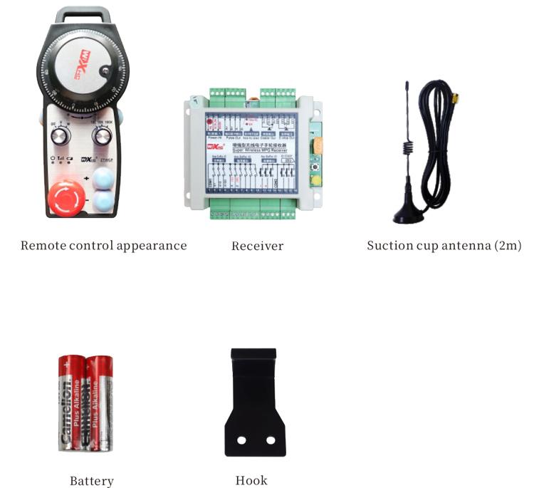
1. Zamontuj odbiornik w skrzynce elektrycznej poprzez klamrę z tyłu, lub zainstaluj go w szafce poprzez otwory na śruby w czterech rogach odbiornika.
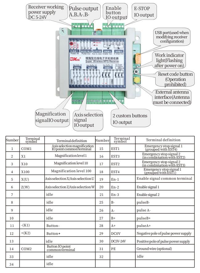
2. Zapoznaj się ze schematem okablowania odbiornika i porównaj go ze sprzętem na miejscu. Podłącz sprzęt do odbiornika za pomocą kabli.
3.Po prawidłowym zamocowaniu odbiornika, antena wyposażona w odbiornik musi być podłączony, a zewnętrzny koniec anteny powinien być zainstalowany lub umieszczony na zewnątrz szafki elektrycznej. Zaleca się umieszczenie go na górnej części szafki elektrycznej, aby uzyskać najlepszy efekt sygnału. Zabrania się pozostawiania anteny niepodłączonej lub umieszczania jej w szafce elektrycznej, ponieważ może to spowodować, że sygnał będzie bezużyteczny.
4. Wreszcie, włącz wyłącznik zasilania koła zamachowego, i możesz sterować maszyną zdalnie za pomocą pokrętła.
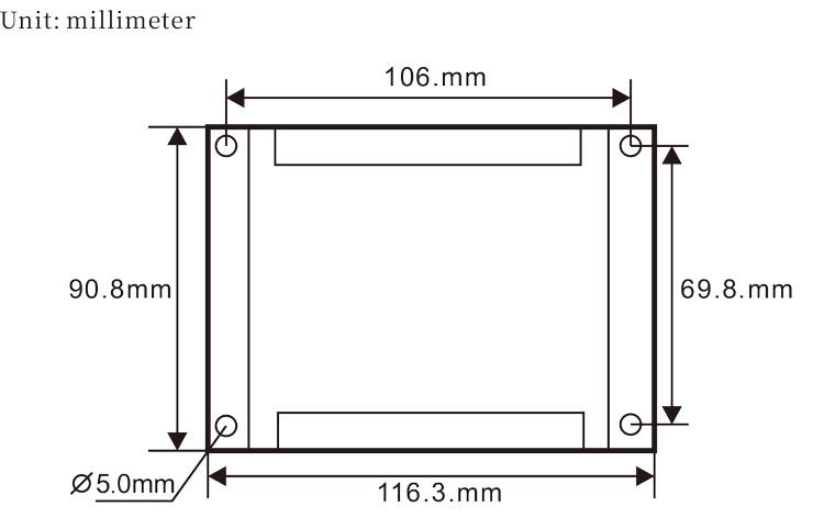
6.2 Wymiary instalacji odbiornika
6.3 Schemat odniesienia okablowania odbiornika
7. Instrukcje działania produktu
1. Włącz maszynę i odbiornik. Kontrolka pracy odbiornika miga. Zamontować baterię w bezprzewodowym elektronicznym pokrętle ręcznym, zabezpiecz pokrywę baterii, I
włącz wyłącznik zasilania bezprzewodowego elektronicznego kółka ręcznego. Świeci się kontrolka poziomu naładowania akumulatora koła zamachowego.
2. Wybierz oś współrzędnych: Naciśnij i przytrzymaj przycisk włączania, przełączyć przełącznik wyboru osi, i wybierz oś, którą chcesz operować.
3. Wybierz powiększenie: Naciśnij i przytrzymaj przycisk włączania, przełącz przełącznik powiększenia,i wybierz żądany poziom powiększenia.
4. Ruchoma oś: Naciśnij i przytrzymaj przycisk włączania, wybierz przełącznik wyboru osi, wybierz przełącznik powiększenia, a następnie obróć enkoder impulsowy. Obróć zgodnie z ruchem wskazówek zegara, aby przesunąć
oś dodatnią i przeciwnie do ruchu wskazówek zegara, aby przesunąć oś ujemną.
5. Naciśnij i przytrzymaj dowolny przycisk niestandardowy, i odpowiedni przycisk wyjścia IO odbiornika zostanie włączony. Zwolnij przycisk, i wyjście zostanie wyłączone.
6. Naciśnij przycisk zatrzymania awaryjnego, odpowiednie wyjście IO zatrzymania awaryjnego odbiornika zostanie odłączone, funkcja pokrętła zostanie wyłączona,zwolnić przycisk zatrzymania awaryjnego, wyjście IO zatrzymania awaryjnego zostanie zamknięte, i funkcja pokrętła zostanie przywrócona.
7. Jeśli koło zamachowe nie będzie używane przez dłuższy czas, automatycznie przejdzie w tryb uśpienia, aby zmniejszyć zużycie energii. Kiedy zostanie ponownie użyty, pokrętło można aktywować, naciskając przycisk włączania.
8. Jeśli koło zamachowe nie będzie używane przez dłuższy czas, zaleca się przełączenie wału koła zamachowego do pozycji OFF, wyłącz zasilanie koła zamachowego, i przedłużyć żywotność baterii.
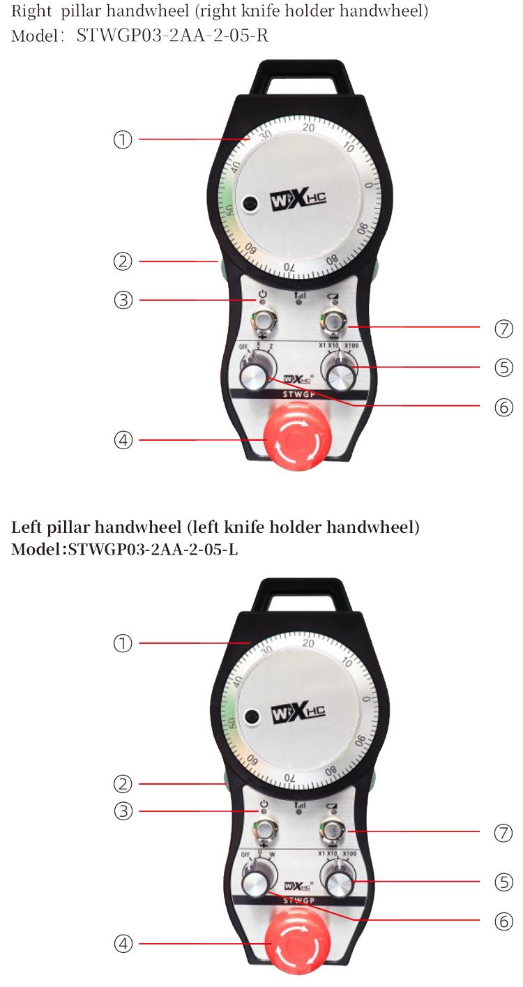
8. Opis modelu produktu

① :ZTWGP reprezentuje styl wyglądu
②:Parametry wyjścia impulsowego:
01: Wskazuje, że sygnał wyjściowy impulsu to A, B; Napięcie impulsowe 5V; ilość impulsów 100PPR.
02:Wskazując, że sygnały wyjściowe impulsów to A i B; Napięcie impulsowe 12V; ilość impulsów 100PPR.
03:Wskazując, że sygnały wyjściowe impulsów to A, B, A -, B -; Napięcie impulsowe 5V; ilość impulsów 100PPR.
04:Wskazuje niski poziom wyjścia obwodu otwartego NPN, z impulsowymi sygnałami wyjściowymi A i B;Liczba impulsów wynosi 100PPR.
05:Wskazuje wysoki poziom sygnału wyjściowego PNP, z impulsowymi sygnałami wyjściowymi A i B; Liczba impulsów wynosi 100PPR.
③:Reprezentuje liczbę przełączników wyboru osi, 2 reprezentuje 2 osie.
④:Reprezentuje typ sygnału przełącznika wyboru osi, A oznacza sygnał wyjściowy punkt-punkt, i B oznacza zakodowany sygnał wyjściowy.
⑤:Reprezentuje typ sygnału przełącznika mnożenia, A oznacza sygnał wyjściowy punkt-punkt, i B oznacza zakodowany sygnał wyjściowy.
⑥:Reprezentuje liczbę przycisków niestandardowych, 2 reprezentuje 2 Niestandardowe przyciski.
⑦:Reprezentuje zasilanie koła ręcznego systemu, I 05 oznacza zasilanie 5V.
⑧:L reprezentuje lewą kolumnę (lewy uchwyt noża), i R oznacza prawą kolumnę (prawy uchwyt noża).
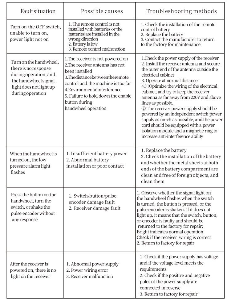
9.Rozwiązanie usterek produktu
1. Użyj go w suchym środowisku w temperaturze pokojowej i nacisku, aby przedłużyć żywotność usług.
2. Unikaj używania w nienormalnych środowiskach, takich jak deszcz i bąbelki wody, aby przedłużyć żywotność serwisową.
3. Aby przedłużyć jego żywotność, należy utrzymywać wygląd pokrętła w czystości.
4. Proszę unikać ściskania, spadający, zderzanie się, itp. aby zapobiec uszkodzeniu precyzyjnych elementów wewnątrz pokrętła lub błędom dokładności.
5. Jeśli nie jest używany przez długi czas, proszę przechowywać koło zamachowe w czystym i bezpiecznym miejscu. Podczas przechowywania i transportu, Należy zwrócić uwagę na odporność na wilgoć i wstrząs.
11. Informacje o bezpieczeństwie
1. Przed użyciem uważnie przeczytaj instrukcje i zabraniaj nie profesjonalistom działalności.
2. Baterię należy wymieniać w odpowiednim czasie, gdy poziom baterii jest zbyt niski, aby uniknąć błędów spowodowanych niewystarczającą mocą baterii i niemożnością obsługi koła zamachowego.
3. Jeśli wymagana jest naprawa, Skontaktuj się z producentem. Jeśli szkody jest spowodowane samowystarczalnymi naprawą, Producent nie udzieli gwarancji