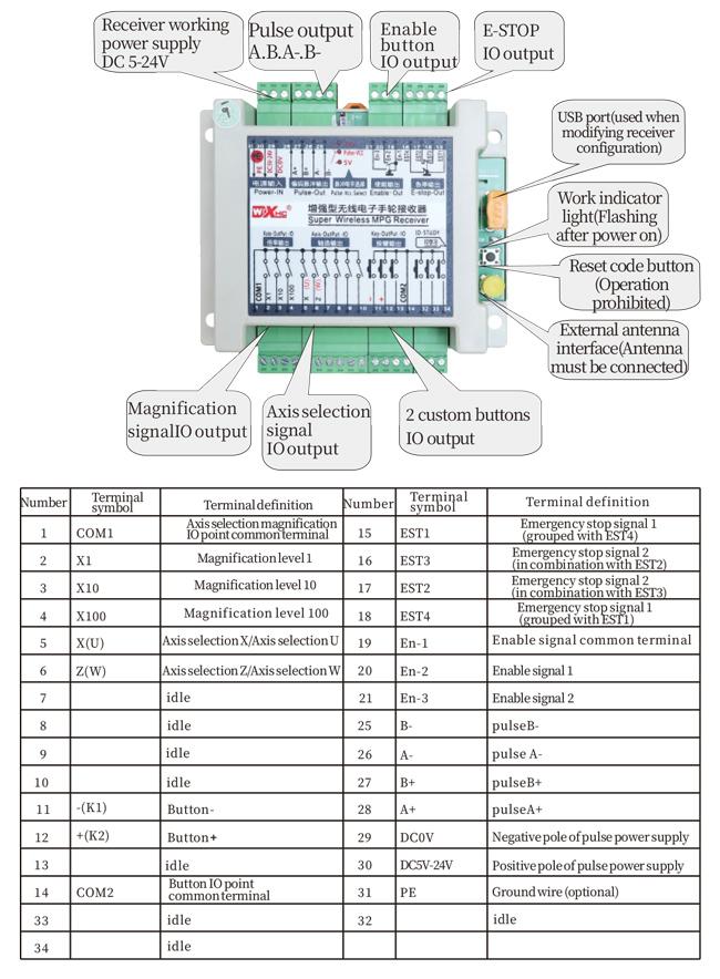
Ts'ehetso 2 likonopo tse ratoang, Ka tlhahiso ea switch ea IO;
Ts'ehetso -2 taolo ea axis;
Ts'ehetso ea Taolo ea Matla a 3;
1.Selelekela sa Product
2. Litšobotsi tsa Ts'ebetso ea Sehlahisoa
| Matla a sebetsang le a hona joale a remote ya waelese |
3V/14MA
|
| Litlhaloso tsa betri | 2 AA libeteri tsa alkaline, boholo 5 |
| Lethathamo la alamo e tlase ea voltage ea remote ea waelese | < 2.3V |
| Mokhethoa oa Mokhethoa oa motlakase | DC5V-24V/A |
| Lethathamo la phalliso ea ho emisa ka tšohanyetso ea moamoheli | AC125V-1A/DC30V-2A |
| Moamoheli o nolofalletsa mefuta e mengata ea lintho tse hlahisoang |
AC125V-1A/DC30V-2A
|
| Receiver custom output load range | DC24V/50mA |
| Lethathamo la phalliso ea phalliso ea axis ea ho amohela | DC24V/50mA |
| Lethathamo la phalliso ea moamoheli | DC24V/50mA |
| Matla a phetiso ea terminal e tšoaroang ka letsoho |
15dBm
|
| Moamoheli ea amohelang maikutlo | -100dBm |
| Maqhubu a puisano a se nang mohala | 433Sehlopha sa maqhubu a MHz |
| Sebaka sa puisano se se nang mohala | Mothibelo sebaka sa mahala sa 40 Metres |
| Mocheso oa ts'ebetso | -25℃ < X < 55℃ |
| Bophahamo ba hoetla | 1 (Meter) |
| Bongata ba konopo ea tloaelo | 2 |
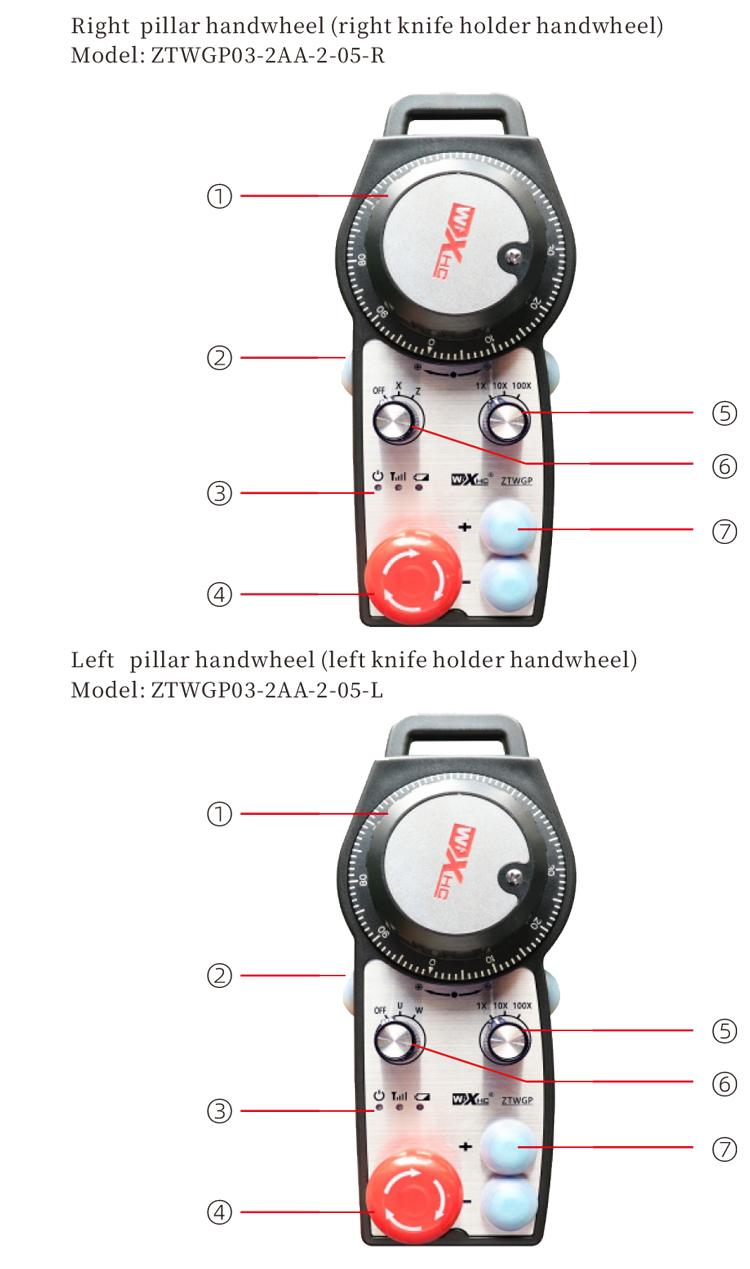
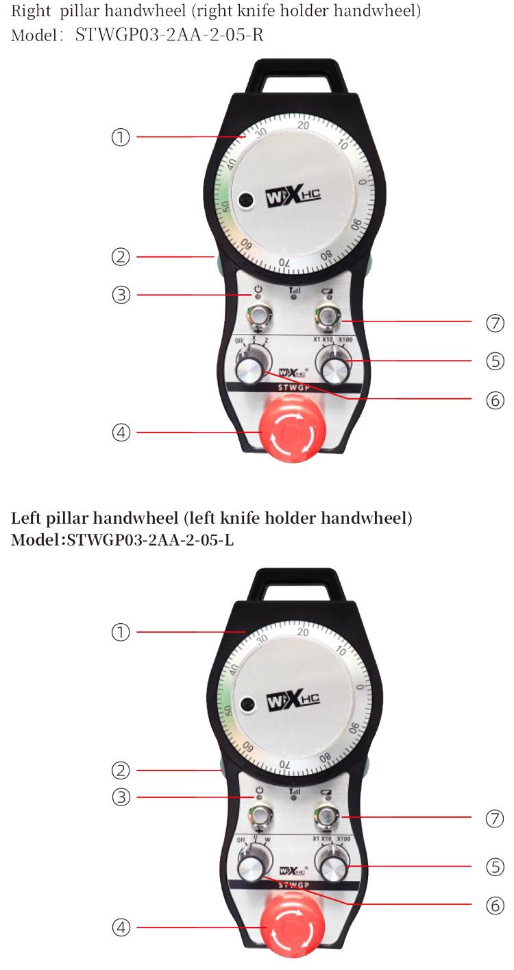
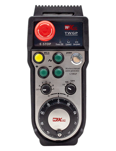
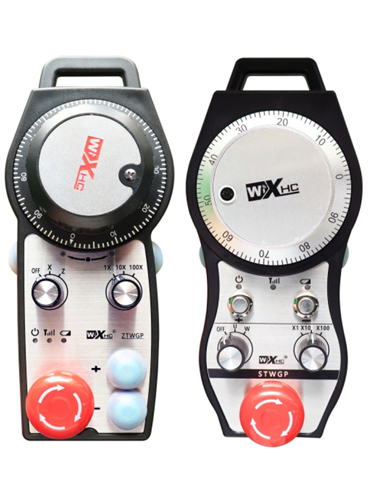
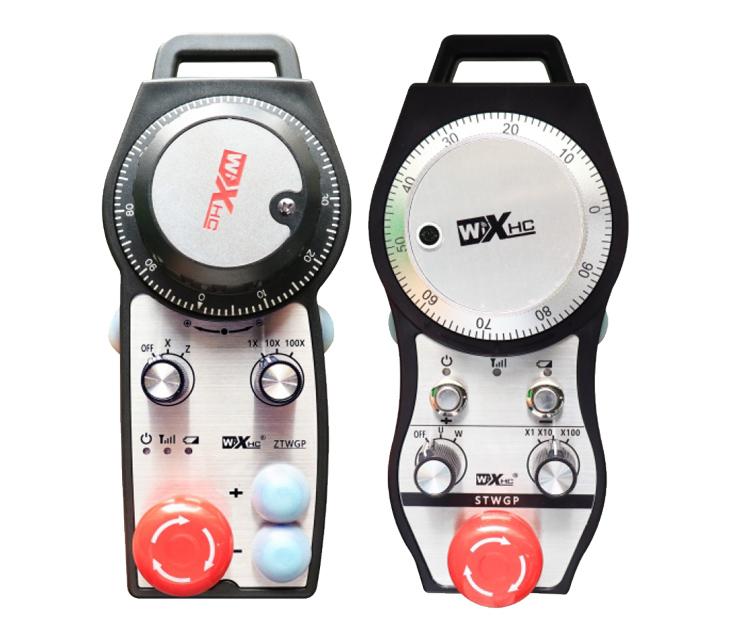
① Pulse encoder:
Tobetsa le ho ts'oara konopo ea ho nolofalletsa, sisinya ena, Emisa letšoao la pulse,le ho laola motsamao oa axis ea mochini.
② Bulela konopo:
Tobetsa konopo efe kapa efe ea bulela ka lehlakoreng le leng, 'me lihlopha tse peli tsa ho nolofalletsa liphetho tsa IO ho moamoheli li tla tsamaisa. Tlosa konopo ea ho nolofalletsa ho hakolla tlhahiso ea IO; 'Me pele u fetola ho holisa khetho ea axis le ho sisinya lebili la letsoho,konopo ea ho nolofalletsa e hloka ho ts'oaroa hore e sebetse; Ts'ebetso ena e ka hlakoloa ka software ea tlhophiso.
③ Mabone a bontšang:
Leseli le lehlakoreng le letšehali: matla kganyeng,lebili la letsoho le sebelisa axis ho khetha TIMA bakeng sa matla, mme lebone lena le dula le bonesitswe kamora hore motlakase o boneswe;
Leseli le bohareng: lebone la sesupo le bonesang ha o sebetsa mosebetsi ofe kapa ofe wa lebidi la letsoho, mme ha e bonese ha ho se na opereishene;
Lebone la lehlakore le letona: Boholo ba alamo ea voltage, boemo ba betri bo tlase,sena se benya kapa se dula se le teng, betri e hloka ho nkeloa sebaka.
④ Konopo ea ho emisa ha ts'ohanyetso:
Tobetsa konopo ea STRED STORE, 'me likarolo tse peli tsa ho emisa tsa tšohanyetso li-ungputs tse mabapi le moamoheli li tla khaoloa, Mesebetsi eohle ea linotsi e tla se sebetse.
⑤ Phetoho ea ho holisa:
Tobetsa 'me u tšoare konopo ea ho bulela ho chencha switjha ea ho holisa, e ka fetolang kgolo e laoloang ke lebili la letsoho.
⑥ Phetoho ea khetho ea axis (Phetoho ea Matla):
Tobetsa o hatelle konopo ea ho bulela ho chencha switjha ea khetho ea axis, e ka fetolang sebaka sa motsamao se laoloang ke lebili la letsoho. Fetolela switch ena ho tloha HO TIMA ho ea ho axis efe kapa efe ebe o bulela matla a lebili la letsoho.
⑦ Konopo e ikhethileng:
Likonopo tse peli tse ikhethileng, e mong le e mong ea lumellanang le ntlha ea uo ea uo.
1. Kenya mochine o amohelang motlakase ka har'a khabinete ea motlakase ka lesela le ka morao, kapa e kenye ka har'a khabinete ka masoba a screw a likhutlong tse 'ne tsa moamoheli.
2. Lebisa ho setšoantšo sa hau sa marang-rang le se bapisoang le lisebelisoa tsa hau tsa marang-rang. Hokela sesebelisoa ho se amohelang ka likhoele.
3.Kamora hore moamoheli a lokisoe hantle, Antena e nang le moamoheli e lokela ho hokahanngoa, 'me ntlha e ka ntle ea antenna e lokela ho kenngoa kapa e behoe ka ntle ho khabinete ea motlakase. Ho khothalletsoa ho e beha kaholimo ho cabinet ea motlakase bakeng sa phello e ntle ka ho fetisisa. Ho thibetsoe ho tlohela antenna e sa kopanngoa kapa ho e beha ka har'a khabinete ea motlakase, kaha sena se ka etsa hore lets'oao le se ke la sebelisoa.
4. Qetellong, bulela sesebelisoa sa motlakase sa lebili la letsoho, mme o ka tsamaisa mochini o le hole o sebelisa lebili la letsoho.
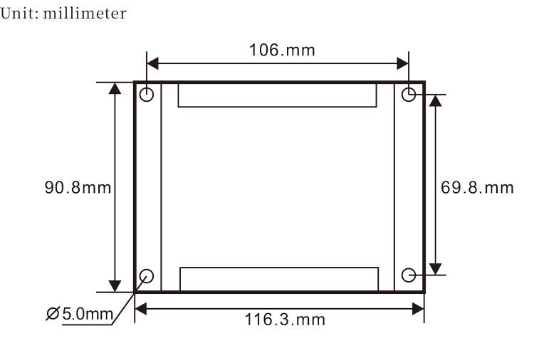
6.2 Tekanyo ea moamoheli
6.3 Ramoa
7. Litaelo tsa ts'ebetso ea sehlahisoa
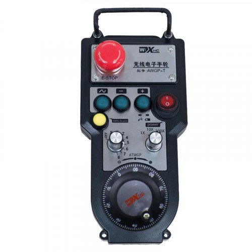
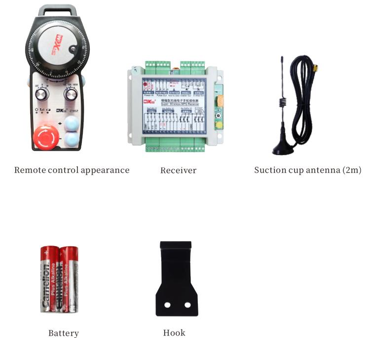
1. Matla ho mochini le moamoheli. Lebone la ho sebetsa la moamoheli lea benya. Kenya betri ka har'a lebili la letsoho la elektroniki la waelese, sireletsa sekoaelo sa betri, mme
bulela sesebelisoa sa motlakase sa lebili la letsoho la elektroniki la waelese. Lebone la boemo ba betri ea handwheel le butswe.
2. Kgetha Axis: Tobetsa le ho ts'oara konopo ea ho nolofalletsa, toggle switjha ya kgetho ya axis, ebe u khetha axis eo u batlang ho e sebetsa.
3. Khetha Bonolo: Tobetsa le ho ts'oara konopo ea ho nolofalletsa, toggle switch ea magnification,ebe u khetha boemo bo lakatsehang ba ho holisa.
4. Ho tsamaisa Axis: Tobetsa le ho ts'oara konopo ea ho nolofalletsa, Khetha phetoho ea axis, Khetha switch ea ho phahamisa, ebe o potoloha sekhouto sa pulse. Fetola ho ea ka tatellano ho tsamaisa
axis positive le counterclockwise ho suthisa axis e mpe.
5. Tobetsa le ho tšoara konopo ea tloaelo, 'me konopo e tsamaellanang le IO tlhahiso ea moamoheli e tla buloa. Lokolla konopo, mme tlhahiso e tla tingwa.
6. Tobetsa konopo ea STRED STORE, Sebaka sa maemo a tšohanyetso a io se tsamaeang le moamoheli se tla felisoa, Ts'ebetso ea letsoho le matsoho e tla holofala,Lokolla konopo ea SIRGEND STORE, Kameho ea tšohanyetso ea boemo ba IO e tla koaloa, le ts'ebetso ea letsoho la letsoho e tla khutlisoa.
7. Haeba maqhubu a letsoho ha a sebetse nako e telele, e tla kena ka mokhoa oa ho robala ho fokotsa tšebeliso ea matla. Ha e sebelisoa hape, handwheel e ka kengoa tšebetsong ka ho tobetsa konopo ea nolofalletsa.
8. Haeba li-handheel ha li sebelisoe nako e telele, ho kgothaletswa ho fetola shaft ya handwheel ho boemo ba OFF, tima matla a matsoho, ebe o holisa bophelo ba betri.
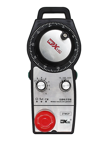
8. Tlhaloso ea mohlala oa sehlahisoa

① :ZTWGP e emela mokhoa oa ponahalo
②:Ho pullisa litekanyetso:
01: E bontša hore lets'oao la pulse output ke A, B; Volse voltage 5v; pulse quantity 100PPR.
02:Ho bonts'a hore mats'oao a pulse ke A le B; Pulse voltage 12V; pulse quantity 100PPR.
03:Ho bonts'a hore mats'oao a pulse ke A, B, A -, B -; Volse voltage 5v; pulse quantity 100PPR.
04:E supa tlhahiso e tlase ea potoloho e bulehileng, ka lipontšo tsa ho hlahisoa ha ho hlahisoa ha li-le b;Palo ea likhahla ke 100PPR.
05:E bonts'a tlhahiso e phahameng ea Pnp PRNP, ka lipontšo tsa ho hlahisoa ha ho hlahisoa ha li-le b; Palo ea likhahla ke 100PPR.
③:E emelang palo ea li-switches tsa khetho ea axis, 2 e emela 2 Axes.
④:E emela mofuta oa lets'oao la ho khetha axis, E emela lets'oao la ho kenya lintlha, le B e emela letšoao la tlhahiso ea tlhahiso.
⑤:E emela mofuta oa lets'oao la ho atisetsa, E emela lets'oao la ho kenya lintlha, le B e emela letšoao la tlhahiso ea tlhahiso.
⑥:E emela palo ea likonopo tse ikhethileng, 2 e emela 2 likonopo tsa moetlo.
⑦:E emela phepelo ea motlakase bakeng sa handwheel ea sistimi, mme 05 e emela phepelo ea matla a 5V.
⑧:L e emela kholomo e ka ho le letšehali (sets'oere sa thipa se letšehali), mme R e emela kholomo e nepahetseng (setshoaro sa thipa se letona).
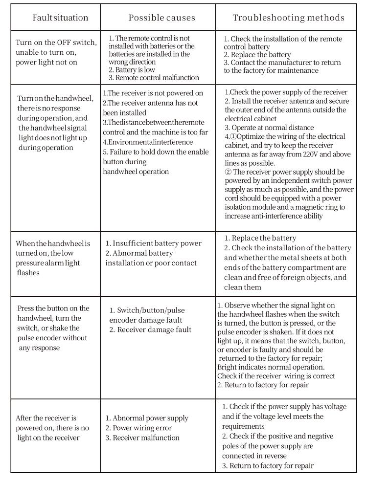
9.Tharollo ea ho Se sebetse hantle ha Sehlahisoa
1. Ka kopo e sebelise tikolohong e omeletseng ka mocheso oa kamore le khatello ea ho eketsa bophelo ba bona.
2. Ka kopo qoba ho sebelisa tikolohong e sa tloaelehang joalo ka ha pula le likhoho tsa metsi li ka eketsa bophelo ba tšebeletso.
3. Ka kopo boloka ponahalo ea makhasi a bonoa a hloekisitse bophelo ba bona.
4. Ka kopo qoba ho teba, ho oela, ho thothomela, etc. Ho thibela tšenyo ea likarolo tse mabapi le ka hare ho letsoho kapa ho nepahala ha liphoso.
5. Haeba e sa sebelisoe nako e telele, Ka kopo boloka letsoho la letsoho le le leng sebakeng se hloekileng le se sireletsehileng. Nakong ea polokelo le lipalangoang, Tlhokomeliso e lokela ho lefuoa ho mongobo le ho tšoha.
11. Tlhahisoleseling ea polokeho
1. Ka kopo bala litaelo ka hloko pele li sebelisoa le ho thibela litsebi tse sa sebetseng.
2. Ka kopo khutlisetsa betri ka nako ha boemo ba betri bo le tlase haholo ho qoba liphoso tse bakoang ke matla a sa lekaneng a betri le ho se khone ho tsamaisa lebili la letsoho..
3. Haeba ho lokisoa ho hlokahala, Ka kopo ikopanye le moetsi. Haeba tšenyo e bakoa ke ho lokisa, Moetsi a ke ke a fana ka waranti