Descripción
1.Modelo de producto
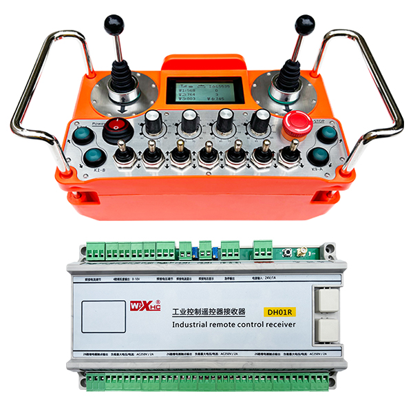
Modelo: DH01R-4W-26K
Equipo aplicable:Varios equipos industriales
2.Diagrama de accesorios de productos
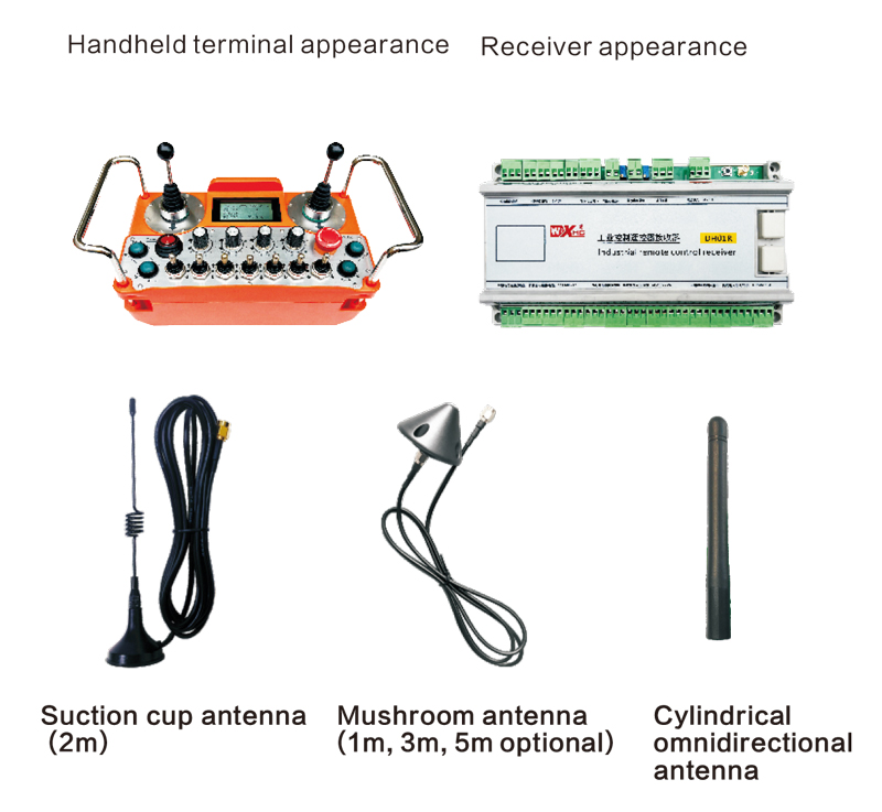
Nota: Puedes elegir una de las tres antenas. La antena de la copa de succión es estándar de forma predeterminada.
3.Descripción del modelo de producto
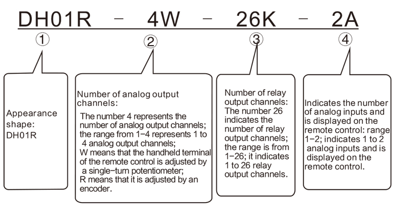
Nota:
SERIE DH01R, Si el sufijo contiene t, Significa con la salida de parada de emergencia;sin t, Significa sin salida de parada de emergencia.
Si no hay salida analógica, no hay necesidad de observar 0w o 0r; las analogquantidades w1, W2, W3, y W4 predeterminado a la salida de voltaje analógico de 0-10V; al mismo tiempo, W1 y W2 se pueden ampliar a 2 salidas de potenciómetro digital aislado, con una variedad de 0 -5K ohms, ½ vatio; resolución: 20 ohmios. Los dos potenciales digitales se pueden usar para controlar la corriente de soldadura y el voltaje de soldadura de la máquina de soldadura. Si se requiere la salida del potenciómetro digital, Se requieren notas de usuario.
④ Entrada de análisis, que se extiende desde 1 a 2, indicando que hay 1 a 2 entradas analógicas(máximo 2 canales); Cuando hay una entrada analógica, Debe tener en cuenta el rango de voltaje de la entrada analógica (Nuestro receptor predeterminado es 0 -5V, el usuario también puede notar como 4-20 MA o 0-10V, etc.) y el rango de visualización correspondiente de la cantidad analógica (Por ejemplo: mostrar 0-100 voltios o 0-1000 amperios)
Estas dos cantidades analógicas se pueden usar como pantallas para la corriente de soldadura y el voltaje de soldadura.
4.Características
1)Máximo 26 salidas de retransmisión;
2)Máximo 4 canales de salida analógica de 0-10V (El rango de visualización se puede personalizar): soporte 2 canales de salida de potenciómetro digital aislado extendido;
3)2 entradas analógicas; y se muestra en el control remoto, El rango de visualización se puede personalizar
4)1 canales de salida de relé de parada de emergencia contactos normalmente cerrados;
5) Desarrollado por 3 Baterías AA, diseño de bajo consumo de energía;
6) La distancia de operación inalámbrica es 200 medidores;
7)Grado de protección IP67;
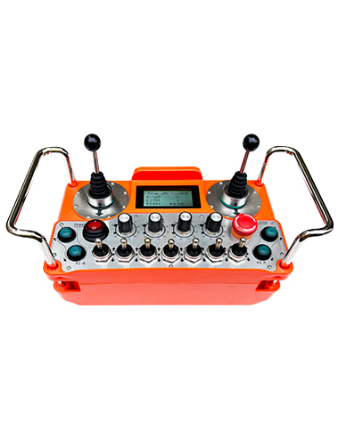
8)Con operación de interruptor cruzado, admite dos interruptores cruzados de 4 direcciones;
9)Diseño de correa trasera.
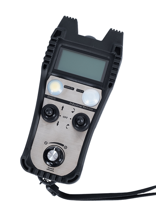
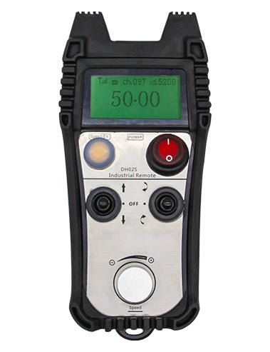
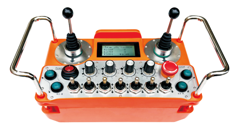
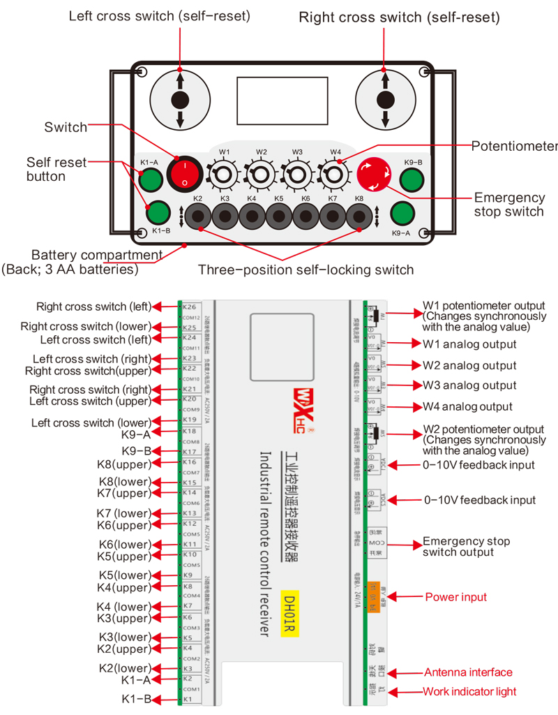
5.Descripción del interruptor de control remoto
6.Mostrar introducción al contenido
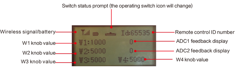
Valor del mando W1: W1: 0-1000 (parámetro ajustable 0-9999)
Valor de la perilla W2: W2: 0-5000 (parámetro ajustable 0-9999)
Valor de la perilla W3: W3: 0-5000 (parámetro ajustable 0-9999)
Valor de la perilla W4: W4: 0-5000 (parámetro ajustable 0-9999)
Pantalla de retroalimentación ADC1: 0-1000 (parámetro ajustable 0-5000)
Pantalla de retroalimentación ADC2: 0-1000 (parámetro ajustable 0-5000)

Bajo voltaje: La batería del control remoto está demasiado baja, por favor reemplace la batería.

Red caída: La señal inalámbrica está interrumpida.. Comprueba la potencia del receptor., enciéndelo de nuevo, y reinicie el control remoto.
7.Instrucciones de funcionamiento de la función de control remoto
1) Encienda el control remoto
Cuando el receptor está encendido, El indicador de trabajo del receptor parpadea; Instale dos baterías AA en el control remoto, Encienda el interruptor de encendido, y la pantalla muestra un valor,indicando una startup exitosa. La luz indicadora de trabajo del receptor se vuelve sólida.
2) Funciones de interruptor y botón
Cualquier funcionamiento del interruptor de giro y el botón en el control remoto puede controlar el punto de salida de la señal del interruptor correspondiente en el receptor. Todos los puntos de salida de la señal de interruptor en el receptor normalmente son señales abiertas de forma predeterminada;
3) Ajuste de velocidad W1-W4
Gire las perillas en W1-W4 arbitrariamente para operar la señal de salida analógica correspondiente o la señal de potenciómetro en el extremo del receptor. La señal de salida analógica en el extremo del receptor es predeterminado a una señal de voltaje de 0-10V, y la señal de potenciómetro predeterminada es 0-5k;
4) Función de parada de emergencia
Cuando se presiona el botón de parada de emergencia, Todas las salidas de señal de interruptor están desconectadas y la salida analógica está desconectada; Después de que se libere la parada de emergencia, Todas las señales de interruptor se restablecen y se restaura la salida analógica; 5 segundos después de que se apague el control remoto, Todas las salidas de señal de interruptor se desconectan y las cantidades analógicas permanecen sin cambios. Cuando se enciende el control remoto, las salidas de la señal de conmutación se recuperan automáticamente;
5) Menú de parámetros (Los usuarios tienen prohibido modificarlo en privado)
Algunas funciones del control remoto se pueden ajustar a través de parámetros. Cuando la pantalla w1 = 0, Presione el botón K9-B 3 veces seguidas, y luego presione el botón K9-A 3 veces en una fila para ingresar al menú de parámetros; La tecla K9-A y K9-B a la página a través del menú y seleccione Parámetros; Mantenga presionada K1-A, y luego presione el botón K9-A/B para modificar los parámetros;
Salir del menú de parámetros: Elija guardar o no guardar, y luego presione el botón K1-A para confirmar la salida;
Rango F1W1: El valor de rango de visualización de la perilla W1 en la pantalla, ajustable desde 0 a 9999;
Rango F2W2: El valor de rango de visualización de la perilla W2 en la pantalla, ajustable desde 0 a 9999;
Rango F3W3: El valor de rango de visualización de la perilla W3 en la pantalla, ajustable desde 0 a 9999;
Rango F4W4: El valor de rango de visualización de la perilla W4 en la pantalla, ajustable desde 0 a 9999
Gama F5A1: Valor de rango de visualización de retroalimentación de Mostrar ADC1, 0-5000 ajustable;
Gama F6A2: Valor del rango de visualización de retroalimentación de la retroalimentación ADC2, 0-5000 ajustable;
Corriente de alarma: Establezca el valor de alarma para la pantalla de retroalimentación ADC1 y ADC2. Cuando ADC1 y ADC2 exceden este valor, La pantalla de control remoto se alarmará; Cuando este valor es 0, la función de alarma no es válida;
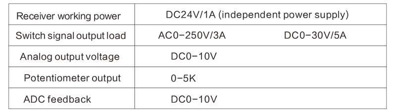
8.Características eléctricas de control remoto
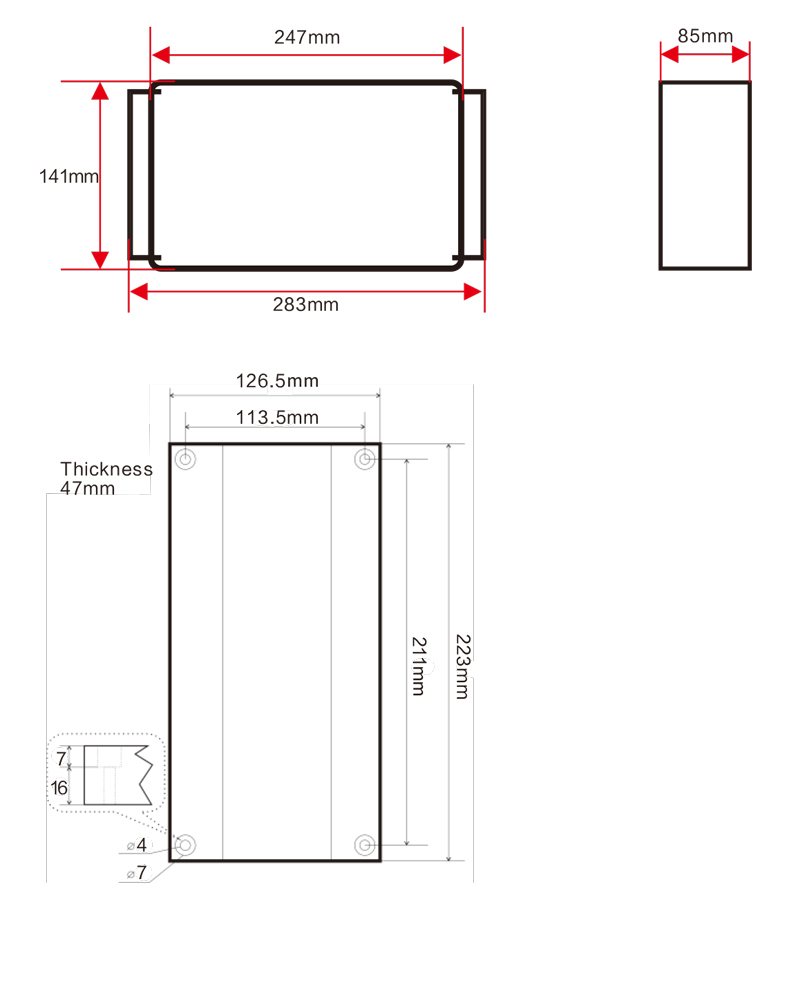
9.Tamaño de control remoto
El derecho de interpretación final de este producto pertenece solo a nuestra empresa.