Descrizione
1. Introduzione del prodotto
Il telecomando per il taglio automatico della sega a fune per vagoni cingolati è adatto per la sega a fune di tipo cingolato
macchine da taglio. Utilizza il 485 Protocollo Modbus RTU per controllare la frequenza del binario sinistro e destro
convertitori, così come il grande avvio del controllo della velocità di conversione della frequenza del motore e la parte anteriore, posteriore,
controller di direzione sinistra e destra. E può leggere la corrente di lavoro della grande frequenza del motore
convertitore attraverso il 485 Protocollo Modbus RTU. Analizzando e confrontando la corrente del
motore di grandi dimensioni, la velocità dei binari sinistro e destro può essere regolata automaticamente in tempo reale
ottenere la funzione di taglio automatico.
2. Caratteristiche funzionali del prodotto
1. Adozione della tecnologia di comunicazione wireless 433 MHz, con una distanza operativa wireless di 100 metri.
2. Adottare la funzione e l'uso automatico del salto di frequenza 32 set di telecomandi wireless
contemporaneamente, senza influenzarsi a vicenda.
3. Supporta tutti i convertitori di frequenza con 485 Protocollo Modbus RTU, e la frequenza attualmente compatibile
le marche di convertitori includono:Shangai Xielin, Fuji, Huichuan, Zhongchen, INVT, E . Per i marchi
che non sono compatibili, contattateci per la personalizzazione.
4. Supporta la regolazione della velocità, di partenza, e lettura della corrente di convertitori di frequenza per motori di grandi dimensioni.
5. Supporta la regolazione della velocità del convertitore di frequenza del binario sinistro e destro, di partenza, anteriore, Indietro, controllo sinistro e destro.
6. Supporta la correzione lineare dei convertitori di frequenza del binario sinistro e destro per mantenere la macchina in movimento
linea retta.
7. Supporta la funzione di taglio automatico della sega a corda, regola automaticamente la velocità della traccia sinistra e destra
tempo reale in base alle informazioni attuali del motore di grandi dimensioni.
8. È inoltre compatibile con il controllo diretto dell'uscita IO per l'avvio e l'arresto del motore, e uscita di tensione analogica
controllo della velocità del motore.
3. Specifiche del prodotto
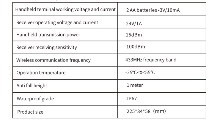
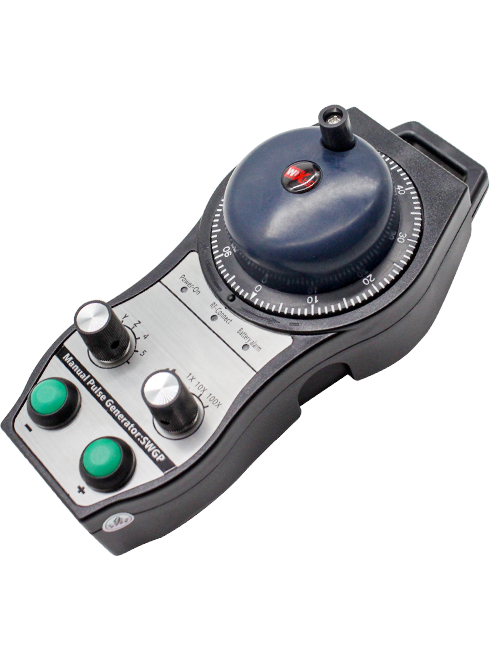
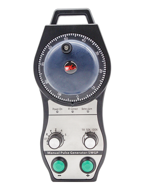
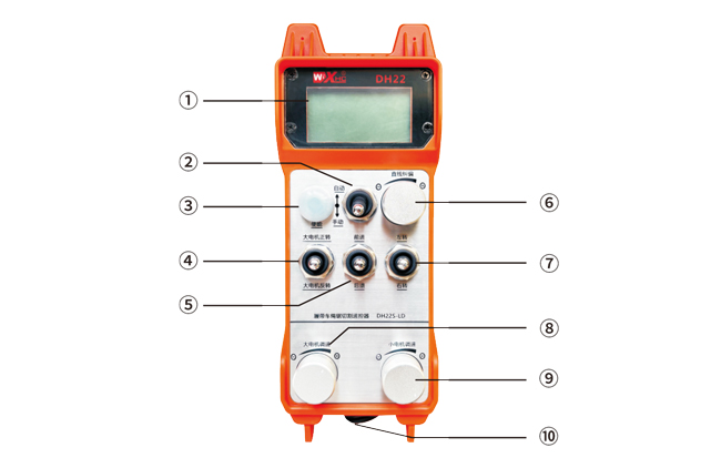
4. Introduzione alla funzione del prodotto
Note:
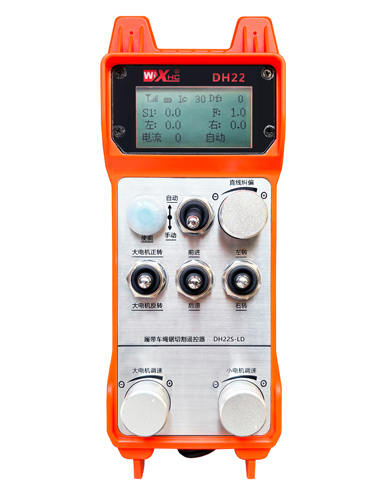
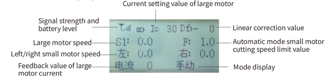
①Visualizzazione sullo schermo:
②Interruttore di modalità:
③Abilita:
Pulsanti combinati, alcune operazioni richiedono di tenere premuto il pulsante di abilitazione per il funzionamento,vedere le istruzioni per ciascun interruttore per i dettagli.
④Grande interruttore del motore:
Utilizzando un interruttore di ripristino a 3 velocità, tirando questo interruttore è possibile controllare la rotazione avanti e indietro del motore grande. Dopo averlo rilasciato, lo Stato rimarrà, e sullo schermo verranno visualizzate le visualizzazioni corrispondenti. La freccia S1↑ indica la rotazione in avanti, e la freccia S1 ↓ indica la rotazione inversa.
⑤Piccolo interruttore avanti/indietro del motore:
Il piccolo motore è dotato di un interruttore autobloccante a 3 velocità davanti. Premendo il pulsante di attivazione e tirando questo interruttore è possibile controllare il piccolo motore per spostarsi avanti e indietro, e la visualizzazione corrispondente apparirà sullo schermo. La freccia ↑↑ rappresenta avanti, e la freccia ↓↓ rappresenta indietro.
⑥ Correzione in linea retta:
Utilizzando una manopola encoder multigiro, premere il pulsante di abilitazione, girare la manopola a destra, e visualizzare la correzione in linea retta: Df: La manopola di rotazione a sinistra aumenta di 1 unità per rotazione, e la sinistra
la velocità del motore aumenta di 0.1 unità; Girare la manopola sinistra, visualizzazione della correzione in linea retta: Df: A destra, ad ogni giro della manopola aumenta di 1 unità, e la velocità del motore destro aumenta
di 0.1 unità.
⑦Piccolo interruttore di rotazione del motore:
Utilizzando un interruttore di ripristino a 3 velocità, quando azionato manualmente, il piccolo motore può essere controllato per girare a sinistra o a destra. Una volta rilasciato, il telecomando interromperà automaticamente questa azione. Nello stato avanzato, quando questo interruttore viene girato, sullo schermo apparirà la visualizzazione corrispondente. La freccia ←↑ indica la svolta a sinistra, e la freccia ↑→ indica la svolta a destra. In modalità retromarcia, ruotare questo interruttore e sullo schermo verrà visualizzata la schermata corrispondente. La freccia ←↓ indica la svolta a sinistra, e la freccia ↓→ indica la svolta a destra.
⑧ Ampia regolazione della velocità del motore:
Utilizzando una manopola encoder multigiro, rotante 1 griglia ogni volta, il valore della velocità del motore grande varia di circa 0.2 unità. La rotazione veloce può modificare rapidamente il valore della velocità del motore di grandi dimensioni.
⑨ Piccola regolazione della velocità del motore:
Utilizzando una manopola encoder multigiro, in modalità manuale, premere il pulsante di attivazione e quindi ruotare una griglia alla volta,il valore della velocità dei motorini sinistro e destro cambia di circa 0.1 unità, e la rotazione rapida può modificare rapidamente il valore della velocità del piccolo motore. In modalità automatica, premere il pulsante di attivazione e ruotare una griglia alla volta,il valore limite di velocità F del motorino varia di circa 0.1 unità. La rotazione rapida può modificare rapidamente il valore limite di velocità del piccolo motore.
⑩ Interruttore di alimentazione del telecomando
Lo schermo del display del telecomando è acceso.
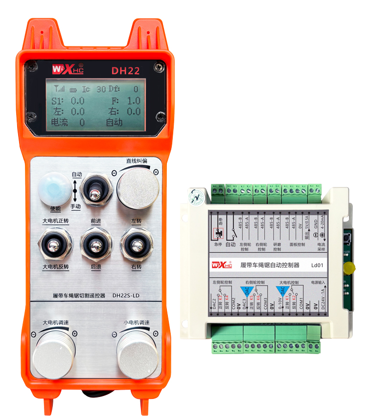
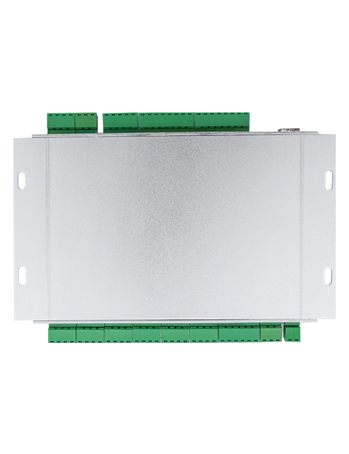
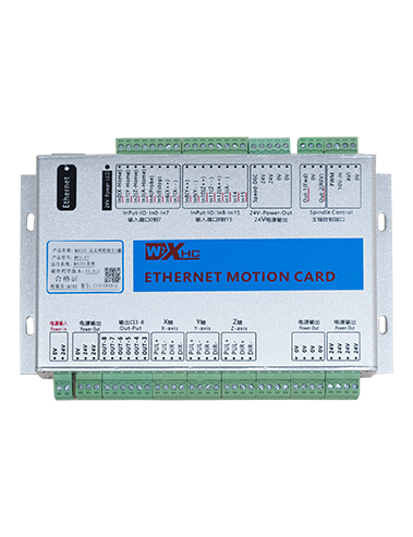
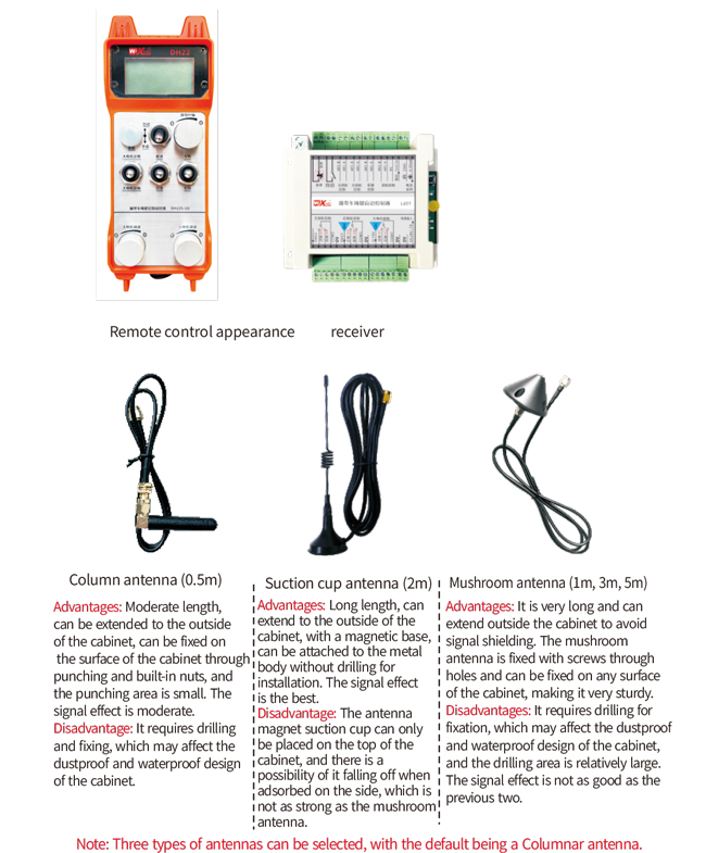
5. Schema degli accessori del prodotto
6. Guida all'installazione del prodotto
6.1 Passaggi di installazione del prodotto
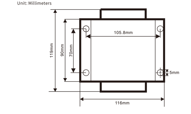
1. Installare il ricevitore nell'armadio elettrico attraverso la fibbia sul retro, oppure installarlo nell'armadio attraverso i fori per le viti ai quattro angoli del ricevitore.
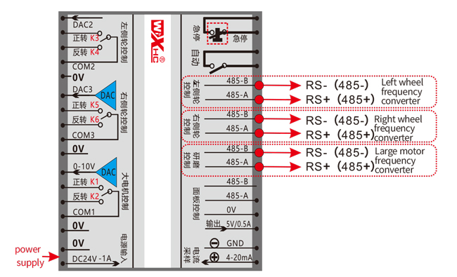
2. Fare riferimento al nostro schema elettrico del ricevitore e confrontarlo con l'attrezzatura in loco. Collegare l'apparecchiatura al ricevitore tramite fili.
3. Dopo aver riparato il ricevitore, è necessario collegare l'antenna dotata di ricevitore ed installare o posizionare l'estremità esterna dell'antenna all'esterno del quadro elettrico. Si consiglia di posizionarlo sulla parte superiore dell'armadio elettrico per ottenere il miglior effetto del segnale. È vietato lasciare l'antenna scollegata o posizionarla all'interno del quadro elettrico, in quanto potrebbe rendere il segnale inutilizzabile.
4. Finalmente, installare la batteria sul telecomando, serrare il coperchio della batteria, e accendere l'interruttore di alimentazione del telecomando. Dopo che il display del telecomando mostra la normalità
interfaccia di lavoro, è possibile eseguire operazioni di controllo remoto.
6.2 Dimensioni di installazione del ricevitore
6.3 Schema di riferimento del cablaggio del ricevitore
7. Istruzioni per l'uso del prodotto
7.1 Impostazioni dei parametri del telecomando
Metodo per inserire i parametri del backend del controllo remoto:
Ruotare l'interruttore della modalità in modalità manuale, regolare la velocità del piccolo motore su 25 su entrambi i lati, O 0, 10, 20, 40, 50 su tutti i lati, e ruotare continuamente l'interruttore avanti del motore grande verso l'alto 3 volte e giù 3 volte;
Usa il “Controllo della velocità del piccolo motore” manopola per girare le pagine, premere il pulsante di abilitazione, quindi ruotare la piccola manopola di controllo della velocità del motore per modificare i parametri. Dopo la modifica, girare la pagina fino alla fine,selezionare “Salva” per uscire, e premere il pulsante di attivazione per uscire dal menu;
I parametri sono i seguenti:
Corrente massima: campo di feedback della corrente del motore di grandi dimensioni, impostare l'intervallo 15-200 A, predefinito 100;
Parametri di controllo della velocità: Modalità automatica, il piccolo motore accelera automaticamente più velocemente o più lentamente,più piccolo è, più veloce, impostare l'intervallo 200-1500, predefinito 800;
Parametro di decelerazione: Impostare il limite superiore che consente la modifica della velocità del motore. Quando la corrente cambia oltre questo valore, si verificherà la decelerazione. Il più piccolo, più veloce sarà la decelerazione dei motori sinistro e destro, con una gamma di 05-12 e un valore predefinito di 06;
Accelerazione a1: Maggiore è la velocità del motore, più velocemente aumenta, con una gamma di 00-06 e un valore predefinito di 01;
Decelerazione a2: Maggiore è la velocità del motore, più velocemente diminuisce, con una gamma di 00-06 e un valore predefinito di 02;
Abilita la regolazione della velocità: È necessario abilitare la regolazione della velocità del piccolo motore? 00 non abilita, 01 abilita, l'impostazione predefinita è 01;
Inizia l'autobloccaggio: Il motore grande mantiene automaticamente l'autobloccaggio dopo il rilascio degli interruttori di marcia avanti e retromarcia?? 00 non regge, 01 tiene, predefinito 01
Camminata massima: velocità massima dei motori sinistro e destro, allineare 10-100, predefinito 50;
Taglio della corrente: corrente di taglio massima, visualizzato sullo schermo come valore IC, allineare 15-160, predefinito 30,
corrispondente a IC: 30 visualizzato sullo schermo. Il limite superiore di questo parametro è 80% della corrente massima;
Limite di velocità predefinito: La velocità di taglio automatica predefinita del piccolo motore quando acceso rientra nell'intervallo di 0-100, con un valore predefinito di 10. Lo schermo visualizza F1.0, e questo parametro è accurato solo quando è impostata la camminata massima 50.
Modalità automatica: Imposta su 00, il cambio automatico/manuale è un cambio di modalità. Imposta su 01, l'interruttore automatico/manuale è impostato sulla posizione automatica, lo schermo del display mostra l'illuminazione, e l'uscita terminale automatica del ricevitore è chiusa. Quando impostato su manuale, il terminale di uscita automatica è scollegato;
Deviazione del limite di velocità: Il limite superiore della velocità di taglio automatico del motore piccolo varia da 00 A 200, con un valore predefinito di 60 e una visualizzazione corrispondente di 6.0 sullo schermo; Limite superiore del valore visualizzato=offset del limite di velocità x 0.1;
Ospite massimo: velocità massima del motore grande, allineare 10-100, predefinito 50;
Attrezzatura MBus (obbligatorio): Selezione del modello di convertitore di frequenza del motore di grandi dimensioni, allineare 00-03, predefinito 03;
00- Shanghai Xielin 01-Fuji
02-INVT 03-Inovance(Zhongchen, Robicon)
Attrezzatura SBUS (obbligatorio): Selezione del modello di convertitore di frequenza per piccoli motori, allineare 00-05, predefinito 03;
00- Shanghai Xielin 01-Fuji
02-INVT 03-Inovance(Zhongchen, Robicon)
04-Anchuanda 05-Nessuno
7.2 Impostazione dei parametri del convertitore di frequenza
1. Selezione della sorgente del comando: Canale di comando di comunicazione
2. Selezione della sorgente di frequenza principale: comunicazione data
3. Velocità di trasmissione: 19200
4. Formato dei dati: Nessuna verifica, formato dei dati<8-N-1>
5. Indirizzo locale: Impostare il convertitore di frequenza sinistro su 1, il giusto convertitore di frequenza 2, E
il grande convertitore di frequenza del motore a 3
7.3 Istruzioni per l'uso del telecomando
1. Accendere la macchina, Accendi il telecomando, accedere al backend del controllo remoto, impostare il
parametri del backend del controllo remoto, impostando principalmente la frequenza del motore piccolo e del motore grande
modelli di convertitori: (saltare questo passaggio se il costruttore della macchina lo ha già impostato);
2. Impostare i parametri del convertitore di frequenza (saltare questo passaggio se il produttore della macchina
l'ha già impostato);
3. Impostare il telecomando in modalità manuale, e quindi utilizzare il telecomando per spostare la macchina
la posizione di lavoro;
4. In modalità manuale, impostare la corrente di taglio del motore grande su IC e la velocità del motore grande
5. Passare alla modalità automatica e impostare il valore F del limite di velocità di taglio per il motore piccolo;
6. In modalità automatica, ruotare l'interruttore del motore grande su avanti per avviare il motore grande, poi girati
il piccolo interruttore del motore per avanzare o invertire, e il telecomando entra nel taglio automatico
modalità per iniziare a tagliare.
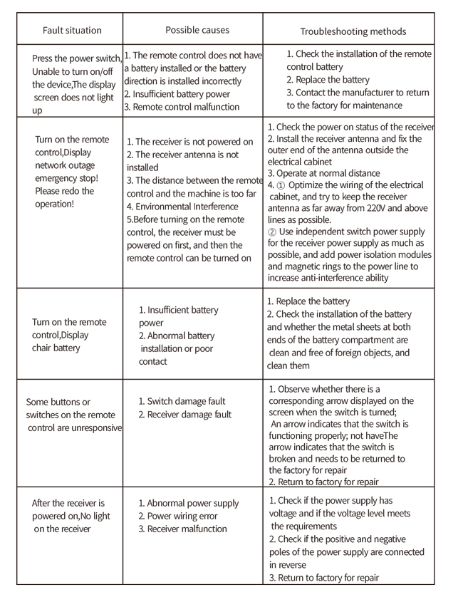
8.Risoluzione dei problemi del prodotto
9.Manutenzione
1. Si prega di utilizzarlo in un ambiente asciutto a temperatura e pressione ambiente per prolungarne la durata.
2. Si prega di evitare l'uso in ambienti anomali come pioggia e bolle d'acqua per prolungarne la durata.
3. Si prega di mantenere puliti il vano batteria e l'area delle schegge metalliche.
4. Si prega di evitare di danneggiare il telecomando a causa di schiacciamenti e cadute.
5. Se non usato per molto tempo, rimuovere la batteria e conservare il telecomando e la batteria in un luogo pulito
e luogo sicuro.
6.Durante lo stoccaggio e il trasporto, è necessario prestare attenzione all'umidità e alla resistenza agli urti.
10. Informazioni sulla sicurezza
1. Si prega di leggere attentamente le istruzioni prima dell'uso e di vietare l'utilizzo ai non professionisti.
2. Si prega di sostituire la batteria in modo tempestivo quando la batteria è troppo scarica per evitare errori causati da
potenza insufficiente, ciò potrebbe impedire il funzionamento del telecomando.
3. Se è richiesta la riparazione, Si prega di contattare il produttore. Se il danno è causato dall'autoriparazione, il produttore
non fornirà garanzia.