应用:用于各种工业设备
1.最大限度 26 继电器输出.
2.无屏障传输距离为 200 仪表.
3. 最大限度 4 模拟0-10V输出的通道 (显示范围可以自定义): 支持 2 扩展孤立的数字电位计输出的通道;
4. 2 模拟输入; 并显示在遥控器上, 显示范围可以自定义.
5. 1 紧急停止继电器输出通常关闭接触.
应用:用于各种工业设备
1.最大限度 26 继电器输出.
2.无屏障传输距离为 200 仪表.
3. 最大限度 4 模拟0-10V输出的通道 (显示范围可以自定义): 支持 2 扩展孤立的数字电位计输出的通道;
4. 2 模拟输入; 并显示在遥控器上, 显示范围可以自定义.
5. 1 紧急停止继电器输出通常关闭接触.
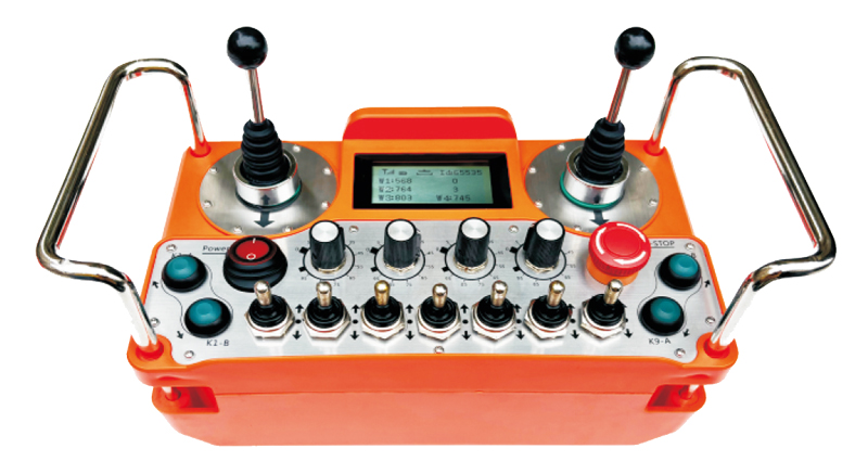
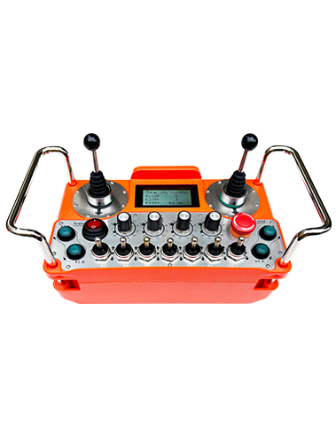
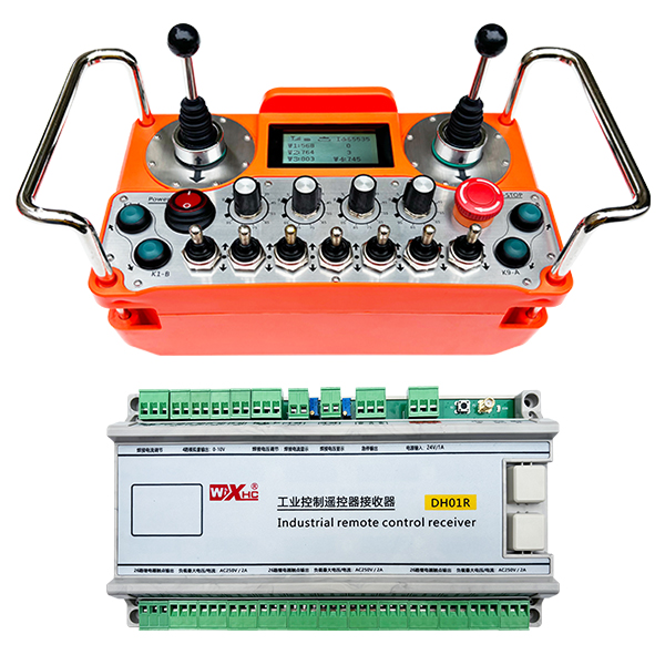
模型: DH01R-4W-26K
适用的设备:各种工业设备
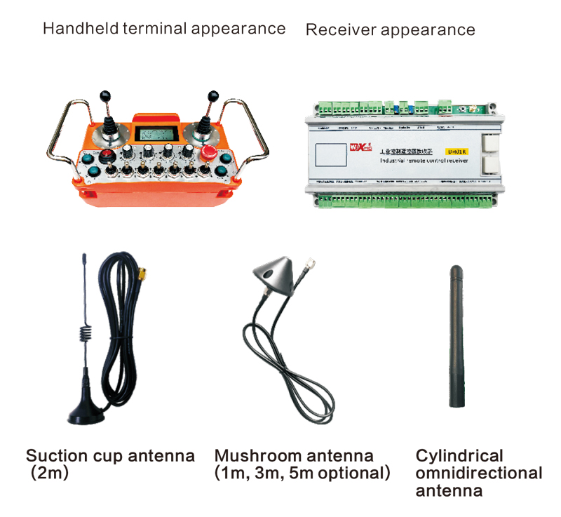
笔记: 您可以选择三个天线之一. 默认情况下,吸入杯天线是标准的.
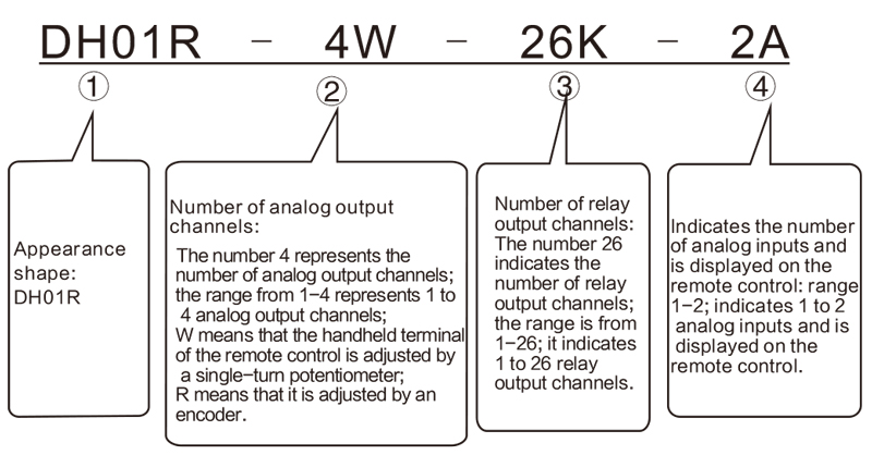
笔记:
① DH01R系列, 如果后缀包含 T, 表示有急停输出;不带T, 表示无急停输出.
②如果没有模拟输出, 无需备注0W或0R; 模拟量 W1, W2, W3, W4默认为0-10V模拟电压输出; 同时, W1和W2可以扩展为 2 隔离数字电位器输出, 与一系列 0 -5千欧姆, ½ 瓦; 解决: 20 欧姆. 两个数字电位可用于控制焊机的焊接电流和焊接电压. 如果需要数字电位器输出, 需要用户备注.
④模拟量输入, 范围从 1 到 2, 表明有 1 到 2 模拟输入(最大限度 2 频道); 当有模拟输入时, 您需要注意模拟输入的电压范围 (我们的接收器默认为 0 -5v, 用户还可以注释为 4-20 mA 或 0-10V, ETC。) 以及模拟量对应的显示范围 (例如: 展示 0-100 伏特或 0-1000 安培)
这两个模拟量可用作焊接电流和焊接电压的显示.
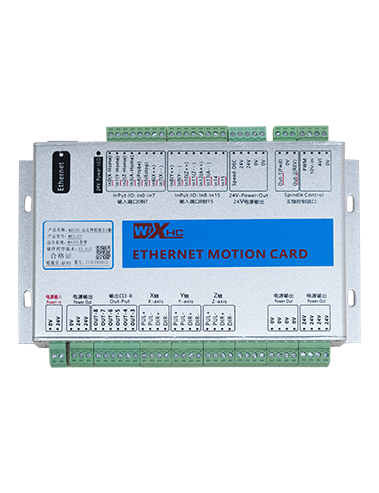
1)最大限度 26 继电器输出;
2)最大限度 4 模拟0-10V输出的通道 (显示范围可以自定义): 支持 2 扩展孤立的数字电位计输出的通道;
3)2个模拟输入; 并显示在遥控器上, 显示范围可以自定义
4)1路急停继电器输出常闭触点;
5) 供电 3 AA电池, 低功耗设计;
6) 无线操作距离为 200 仪表;
7)防护等级IP67;
8)具有十字开关操作, 支持两个4向交叉开关;
9)背带设计.
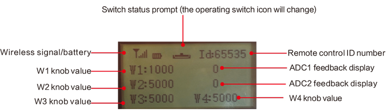
W1旋钮值: W1: 0-1000 (参数可调 0-9999)
W2旋钮值: W2: 0-5000 (参数可调 0-9999)
W3旋钮值: W3: 0-5000 (参数可调 0-9999)
W4旋钮数值: W4: 0-5000 (参数可调 0-9999)
ADC1反馈显示: 0-1000 (参数可调 0-5000)
ADC2反馈显示: 0-1000 (参数可调 0-5000)

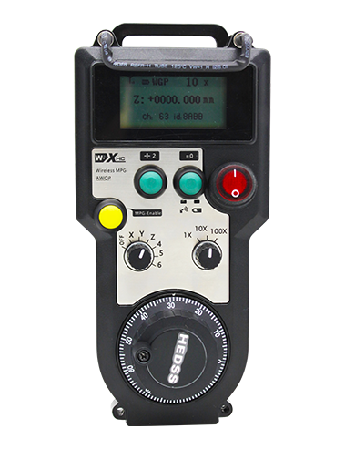
低压: 遥控电池太低, 请更换电池.

网络下降: 无线信号中断. 请检查接收器的功能, 再次为其供电, 并重新启动遥控器.
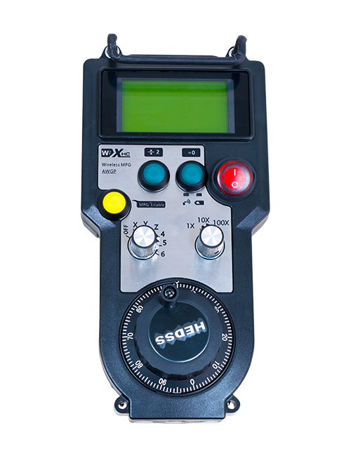
1) 打开遥控器
当接收机开机时, 接收机工作指示灯闪烁; 在遥控器中安装两节 AA 电池, 打开电源开关, 并且显示屏显示一个值,表示成功的启动. 接收机工作指示灯常亮.
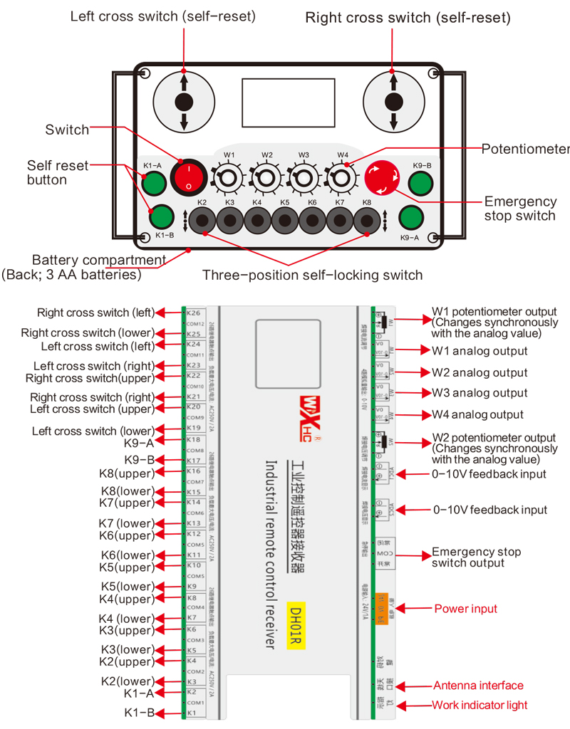
2)开关及按钮功能
任意操作遥控器上的扭动开关和按钮即可控制接收器上相应的开关信号输出点. 接收器上所有开关信号输出点默认为常开信号;
3)W1-W4速度调节
任意旋转W1-W4中的旋钮即可操作接收端对应的模拟输出信号或电位器信号. 接收端模拟输出信号默认为0-10V电压信号, 电位器信号默认为0-5K;
4) 急停功能
按下紧急停止按钮时, 所有开关信号输出断开,模拟输出断开; 紧急停止解除后, 所有开关信号恢复,模拟输出恢复; 5 遥控器关闭后几秒, 所有开关信号输出断开,模拟量保持不变. 当遥控器打开时, 开关信号输出自动恢复;
5)参数菜单 (禁止用户私自修改)
可以通过参数调整遥控器的某些功能. 当显示W1=0时, 按 K9-B 按钮 3 连续多次, 然后按K9-A按钮 3 连续多次进入参数菜单; K9-A 和 K9-B 键用于翻阅菜单并选择参数; 按住K1-A, 然后按K9-A/B按钮修改参数;
退出参数菜单: 选择保存或不保存, 然后按K1-A键确认退出;
F1W1范围: 显示屏上W1旋钮的显示范围值, 可调自 0 到 9999;
F2W2范围: W2旋钮在显示屏上的显示范围值, 可调自 0 到 9999;
F3W3系列: 显示屏上W3旋钮的显示范围值, 可调自 0 到 9999;
F4W4系列: 显示屏上W4旋钮的显示范围值, 可调自 0 到 9999
F5A1系列: 显示ADC1反馈显示范围值, 0-5000 可调节的;
F6A2系列: 显示ADC2反馈显示范围值, 0-5000 可调节的;
报警电流: 设置ADC1和ADC2反馈显示的报警值. 当ADC1和ADC2超过该值时, 遥控器显示屏会报警; 当该值为0时,报警功能无效;
该产品的最终解释权仅属于我们公司.