応用:トラックカーロープソーの自動切断用のリモコンは、トラックタイプのロープソーカッティングマシンに適しています
1. 速度規制をサポートします, 起動, そして、大規模なモーター周波数コンバーターの現在の読み取り.
2. 左右のトラック周波数コンバーター速度レギュレーションをサポートします, 起動, フロント, 戻る, 左右のコントロール.
3. 左および右のトラック周波数コンバーターの線形補正をサポートして、マシンを
直線.
応用:トラックカーロープソーの自動切断用のリモコンは、トラックタイプのロープソーカッティングマシンに適しています
1. 速度規制をサポートします, 起動, そして、大規模なモーター周波数コンバーターの現在の読み取り.
2. 左右のトラック周波数コンバーター速度レギュレーションをサポートします, 起動, フロント, 戻る, 左右のコントロール.
3. 左および右のトラック周波数コンバーターの線形補正をサポートして、マシンを
直線.
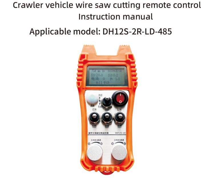
1. 製品の紹介
クローラー車両ロープSAW自動切断リモコンは、クローラーロープソーカッティングマシンに適しています. 485Modbusrtuプロトコルを採用して、左右のクローラーインバーターの速度開始と前後の左方向と右方向の制御を制御します, 左右のクローラーインバーターの速度開始と前後の左方向と右方向の制御を制御するための大きなモーター周波数変換RTUプロトコルと同様に、RTUプロトコル, そして、大きなモーター周波数変換過剰分析と比較, 左右のクローラー速度をリアルタイムで自動的に調整して、自動切断機能を実現します.
2. 製品機能
1. 433MHzワイヤレス通信技術を採用します, ワイヤレス動作距離はです 100 メーター.
2. 自動周波数ホッピング関数を採用します, 使用 32 同時にワイヤレスリモートコントローラーのセット, お互いに影響を与えることなく.
3. 485-Modbus RTUプロトコルですべてのインバーターをサポートします. 適応されたインバーターブランドには含まれます:上海Xielin, 富士, 不安, Zhongchen, invt, アンチャンダ. ブランドがADAでない場合は、カスタマイズについてお問い合わせください.
4. 大型モーターインバーターの開始をサポートします, 速度規制, そして現在の読書.
5. 左右のクローラーインバーター速度調整をサポートします, 始める, 前後の左右のコントロール.
6. 左右のクローラーインバーター直線補正をサポートして、マシンを直線で動かし続ける.
7. サポートロープは、自動切断機能でした, 大きなモーター電流情報に従って、左右のクローラー速度をリアルタイムで自動的に調整します.
8. 同時に, モーターの開始と停止を制御するための直接IO出力と互換性があります, モーター速度を制御するためのアナログ電圧出力.
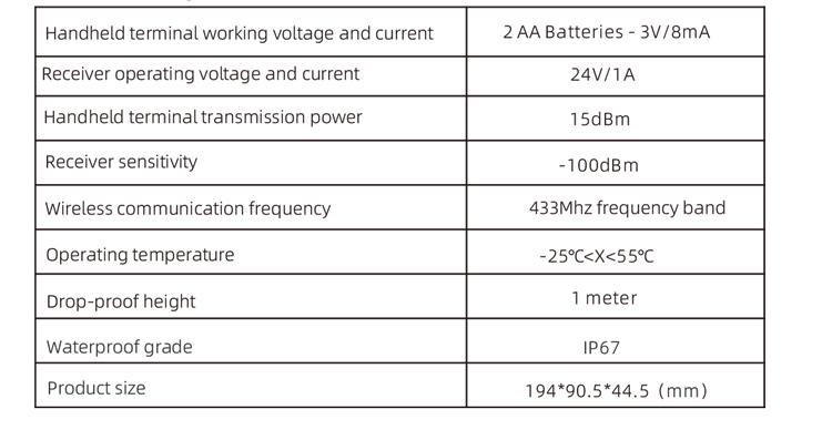
3. 製品仕様
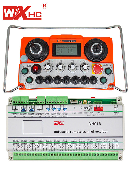
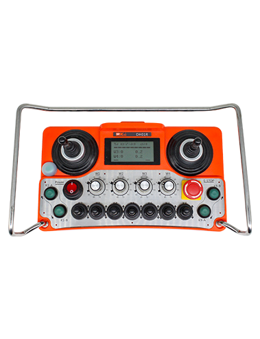
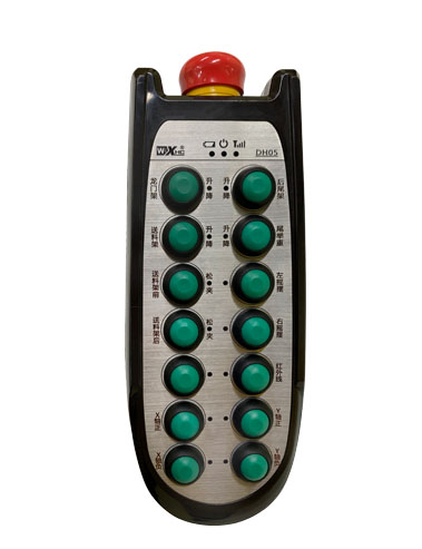
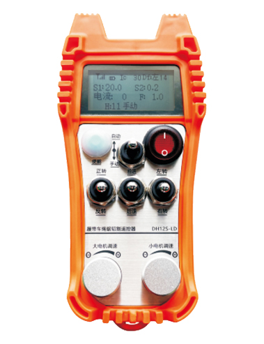
4. 製品機能の紹介
メモ:
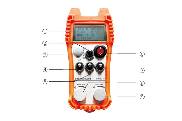
screanディスプレイ:

modeモードスイッチ:
2レベルのスイッチを使用します, 自動モードと手動モードを切り替えることができます, また、対応するモードが画面に表示されます。.
andable enable:
コンビネーションボタン, 一部の操作では、操作のためにイネーブルボタンを押す必要があります, 詳細については、各スイッチの指示を参照してください.
④大型モータースイッチ:
3速リセットスイッチを使用します, このスイッチを引くと、大型モーターの前方回転と逆回転を制御できます. リリースした後, 状態は残ります, また、画面に対応するディスプレイがあります. t矢印は前方回転を示します, y矢印は逆回転を示します.
smallモーターフォワード/リバーススイッチ:
3速セルフロックスイッチを使用します, このスイッチを引くと、小さなモーターを制御して前後に移動できます. 対応するディスプレイは画面に表示されます, t矢印が前方を示し、↓矢印が後方を示す.
controlコントロール電源スイッチを削除します:
リモートコントロールディスプレイ画面がオンになっています.
smallモーターターニングスイッチ:
3速リセットスイッチを使用します, 手動で操作したとき, 小さなモーターを制御して左または右に曲がることができます. 一度リリースされます, リモートコントロールは、このアクションを自動的に停止します。, このスイッチを回すと、対応するディスプレイが画面に表示されます。 + 矢印は左折を示します, そして – 矢印は右折を示します。リバースモードで, このスイッチを回すと、対応するディスプレイが画面に表示されます。 + 矢印は左折を示します, そして – 矢印は右ターンを示します, 次に、このスイッチをターンして、固定ターニング機能を実行します, ターンをより速くします.
olid大きなモーター速度調節:
マルチターンエンコーダーノブを使用します, ノブを回転させて、すべてのために大きなモーターの速度S1を調整します 1 グリッド回転, 大規模なモーターの速度値はおよそ変化します 0.2 ユニット, そして、急速な回転は、大型モーターの速度値を迅速に変更できます.
9 小さな運動速度調節 (線形補正):マルチターンエンコーダーノブを使用します, 手動モードで, すべてのために 1 ノブのターン, 小型モーターの速度値は約 0.1 ユニット. 高速回転は、小さなモーターの速度値を迅速に変更できます.
自動モードで, [イネーブル]ボタンを押して回転させます 1 毎回グリッド. 小型モーターの速度制限値fはおよそ変化します 0.1 ユニット. 迅速な回転は、小さなモーターの速度制限値を迅速に変更できます。, ノブを右に回します, 直線補正ディスプレイはd fを示しています: 左. ノブの各回転は増加します 1 ユニット; 左ノブを回します, 直線補正ディスプレイ: DF: 右. ノブの各回転は増加します 1 ユニット, そして、各補正ユニットは、約 0.02 v.
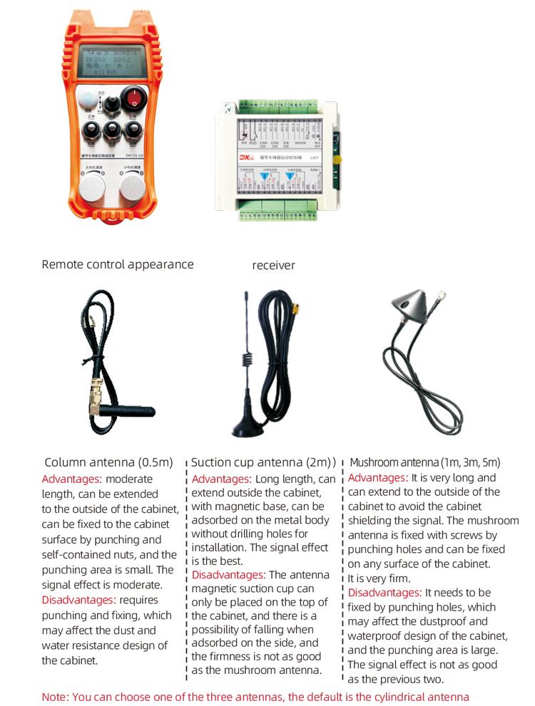
5. 製品アクセサリー図
6. 製品インストールガイド
6.1 製品のインストール手順
1. 後ろのバックルに電気キャビネットにレシーバーを取り付けます, または、レシーバーの四隅にあるネジ穴から電気キャビネットに取り付けます.
2. レシーバー配線図を参照してください, オンサイトの機器を比較してください, 電線を介して機器をレシーバーに接続します.
3. 受信機が固定された後, 受信機を装備したアンテナを接続する必要があります, アンテナの外側の端は、電気キャビネットの外に設置または配置する必要があります. 最良の信号効果を得るために、電気キャビネットの上部に配置することをお勧めします. アンテナを接続しないか、アンテナを電気キャビネット内に置くことは禁じられています, 信号が不十分で使用できない可能性があります.
4. ついに, リモコンにバッテリーを取り付けます, バッテリーカバーを締めます, そして、リモコンの電源スイッチをオンにします. リモートコントロールディスプレイに通常の作業インターフェイスが表示された後, リモートコントロール操作を実行できます.
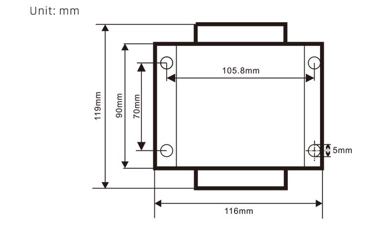
6.2 受信機のインストール寸法
6.3 レシーバー配線参照図

7. 製品操作の指示
7.1 リモートコントロールパラメーター設定
リモートコントローラーの背景パラメーターを入力する方法: モードスイッチをマニュアルモードにします, 小さなモーターの速度を調整します 25, または 0, 10, 20, 40, 50, 大きなモーターのフォワードスイッチを上に回します 3 時間と下向き 3 時代;
を使用します “小さなモーター速度制御” ページをめくるノブ, プレスして、小さなモータースピードコントロールノブをターンしてパラメーターを変更します; 変更後, ページを最後まで回します, [保存]を選択して終了します, [イネーブル]ボタンを押してメニューを終了します;
パラメーターは次のとおりです:最大電流: 大きなモーター電流フィードバック値範囲, 設定範囲15-200A, デフォルト 60;
速度制御パラメーター: 自動モードスモールモーター自動加速速度, 小さいほど速くなります, 設定範囲 200-1500, デフォルト 1000;
減速パラメーター: 許可されるモーター速度の変更の上限を設定する. 現在がこの値を超えて変化したとき, 減速します. 小さいほど, 左右のモーターが速く減速します. 範囲はです 05-12, デフォルトはです 06;
加速A1: 値が大きいほど, モーターの速度が速くなります, 範囲00-06、デフォルト 01; 減速A2: 値が大きいほど, モーター速度が速くなるほど, 範囲 00-06, デフォルト 02;
速度規制を有効にします: 小さなモーター速度調節を有効にする必要があるかどうか, 00 有効になっていません, 01 有効です, デフォルト 01;
スタートアップセルフロック: フォワードスイッチとリバーススイッチがリリースされた後、大きなモーターが自動的にセルフロックを維持するかどうか, 00 維持されていません, 01 維持されます, デフォルト 01;
最大旅行: 左右のモーターの最大速度, 範囲 10-100, デフォルト 50;
カット電流: 最大切断電流, 画面にはIC値が表示されます, 範囲 15-160, デフォルト 30, 画面にICが表示されます: 30. このパラメーターの上限=最大電流x 80%;
デフォルトの速度制限: 起動時のデフォルトの小さなモーター自動切断速度, 範囲 00-100, デフォルト 10, 画面にはF1.0が表示されます, このパラメーターは、最大旅行がに設定されている場合にのみ正確です 50.
ワイヤレスチャネル: デフォルトはです 10. リモートコントロール信号が不安定な場合、またはサイトに信号干渉がある場合, このパラメーターを変更してチャネルを切り替えて干渉を避けることができます;
速度制限オフセット: 小さなモーターの自動切断速度の上限,範囲 00-200, デフォルト 60, 画面が表示されます 6.0; 表示値の上限=速度制限オフセット× 0.1;
最大ホスト: 大型モーターの最大速度, 範囲 10-100, デフォルト 50;
MBUSデバイス ( 必須 ): 大型モーターインバーターモデルの選択, 範囲 00-03, デフォルト 03;
00- 上海Xielin 01 富士
02- invt 03 イノバンス(Zhongchen, ロビコン)
SBUS機器 (必須): 小さなモーター周波数コンバーターモデルの選択, 範囲 00-05, デフォルト 03;
00- 上海Xielin 01 富士
02- invt 03 イノバンス(Zhongchen, ロビコン)
04-Anchuanda 05-None
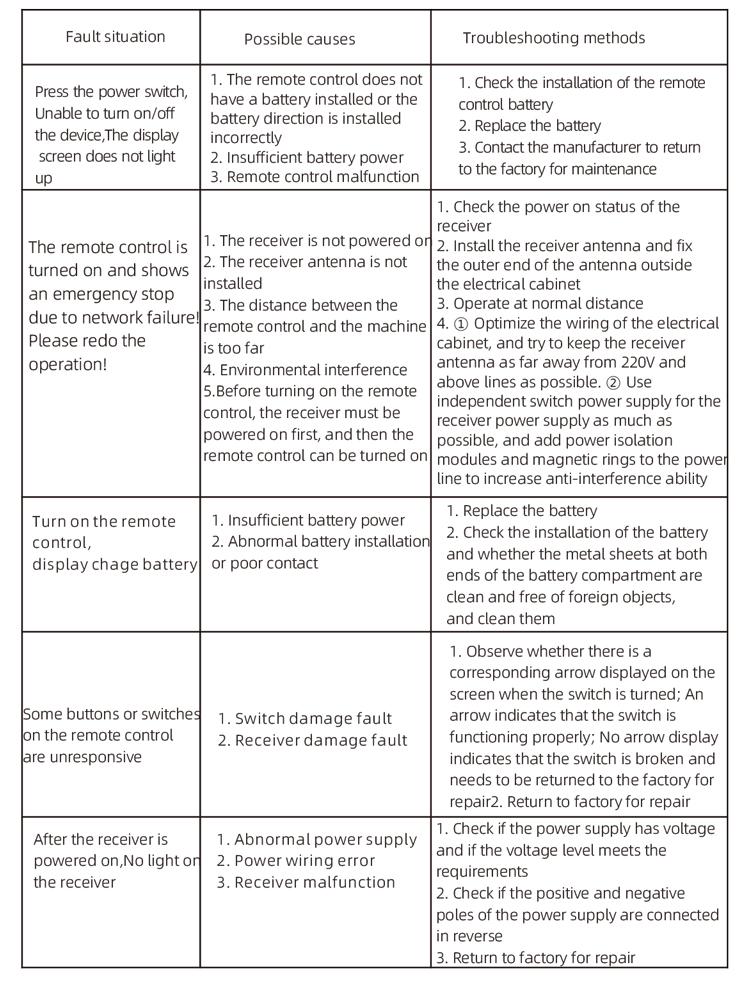
8. 製品のトラブルシューティング
7.2 周波数コンバーターのパラメーター設定
1. コマンドソースの選択: 通信コマンドチャネル
2. 主な周波数ソースの選択: 与えられたコミュニケーション
3. ボーレート: 19200
4. データ形式: 検証なし, データ形式<8-n-1>
5. ローカルアドレス: 左の周波数コンバーターをに設定します 1, 適切な周波数コンバーター 2, および大規模なモーター周波数コンバーター 3
7.3 リモートコントロール操作の手順
1. マシンの電源, リモートコントロールをオンにします, リモートコントロールの背景を入力します, リモートコントロールの背景パラメーターを設定します, 主に、大小のモーター周波数コンバーターのモデルを設定することです (機械メーカーがすでに設定している場合は、この手順をスキップします);
2. 周波数コンバーターのパラメーターを設定します (機械メーカーがすでに設定している場合は、この手順をスキップします);
3. リモートコントロールをマニュアルモードに設定します, そして、リモートコントロールを使用して、マシンを作業位置に移動します;
4. 手動モードで, 大型モーターの切断電流と大型モーターの速度のIC値を設定する;
5. 自動モードに切り替えて、小さなモーターの切削速度制限f値を設定します;
6. 自動モードで, 大きなモータースイッチを転換して前方に回して、大きなモーターを開始します, そして、小さなモータースイッチを前方または逆に変えます. リモートコントロールは自動切断モードに入り、切断を開始します.
9.メンテナンス
1. 室温と圧力の乾燥環境でそれを使用して、そのサービス寿命を延ばしてください.
2. 雨や水の泡などの異常な環境で使用して、サービスの寿命を延ばしないでください.
3. バッテリーコンパートメントと金属製のsh散弾領域をきれいに保ちます.
4. 絞りや転倒のためにリモートコントロールを損傷することは避けてください.
5. 長い間使用されていない場合, バッテリーを取り外して、リモートコントロールとバッテリーを清潔で安全な場所に保管してください.
6.貯蔵および輸送中, 水分と衝撃耐性に注意を払う必要があります.
10. 安全情報
1. 使用する前に指示を注意深く読んで、非専門家が運営を禁止してください.
2. バッテリーが低すぎて電源が不十分であることが原因である場合は、バッテリーをタイムリーに交換してください, リモートコントロールが操作できないようになる可能性があります.
3. 修理が必要な場合, メーカーに連絡してください. 損傷が自己修復によって引き起こされる場合, メーカーは保証を提供しません